What is Partial Discharge in an Inverter-Driven Motor?
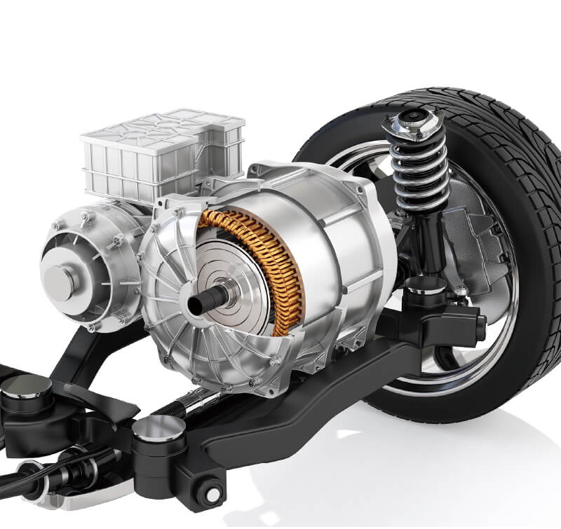
An inverter-driven motor, also known as an inverter-fed motor, is a system that combines a control circuit and a motor. This system utilizes a variable frequency drive (VFD) to convert AC power to DC power and then back into a variable AC power supply. The VFD within the inverter-driven motor system controls the converted DC power through high-speed switching, allowing for precise regulation of the motor's speed and current. In comparison to motors directly powered by commercial power supplies, inverter-driven motors exhibit superior energy efficiency due to the precise control. This system is utilized in various applications such as home appliances and vehicles. For example, in electric vehicles (EVs), inverters convert DC power from the battery into AC power to drive the electric motors.
The rapid switching within the inverter can accelerate the electrical deterioration of the motor. As shown in Figure 1, during the high-speed switching process, surge voltages are generated. These instantaneous high voltages, often exceeding twice the switching voltage, induce momentary high voltages across the motor windings. When these voltages surpass a critical threshold, partial discharges occur between the surfaces of the winding insulation. This phenomenon is known as 'partial discharge.
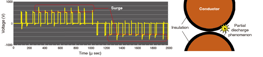 Fig. 1: Surge voltage generated due to inverter switching
Why does partial discharge occur?
As illustrated in Figure 2, the fundamental components of an inverter-driven motor are the rotor and stator. Essentially, the stator comprises coils wound around a stator core. The conductive wires within these coils are insulated by an enamel coating. Subsequently, these wires are further insulated from the stator core by insulating-paper. During the manufacturing process, various factors can compromise the integrity of the insulation. These include misalignment or tearing of the insulating-paper, as well as damage to the enamel coating, such as tears or crushing. These issues can lead to unintended contact between wires or between the windings and the stator core. Such contact compromises insulation performance, ultimately increasing the likelihood of partial discharge. Moreover, voids within the enamel, arising from trapped air bubbles or impurities, and scratches on the enamel surfaces also contribute to the occurrence of partial discharges.
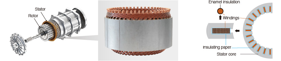 Fig. 2: Basic structure of an inverter-driven motor
Risk of partial discharge
High-voltage inverter-driven motors, such as those found in EVs, are more prone to partial discharge phenomena. In general, partial discharge occurs when a voltage greater than approximately 350 V is applied to a poorly insulated winding. Consequently, not only inverter-driven motors but also high-voltage industrial motors are susceptible to this risk. Partial discharges occur in areas of the motor winding where insulation integrity is compromised. These discharges further exacerbate insulation degradation over time. The progressive deterioration of insulation, stemming from these partial discharges, can ultimately lead to severe consequences, including fires due to short-circuits and complete insulation breakdowns.
How are partial discharges detected?
Partial discharges can be detected through the implementation of dedicated testing procedures. As shown in Table 1, two distinct types of partial discharge tests are commonly employed. Since each test methodology possesses the capability to identify insulation defects in different locations of motor windings, it is imperative to conduct both tests comprehensively to ensure a thorough evaluation of the insulation system's integrity.
Table 1: Partial discharge test types
| Type of test | Description | Purpose |
|---|---|---|
| AC partial discharge | A high AC voltage is repeatedly applied while the charge quantity (pC) of the discharge is measured based on the current waveform. Since typically using a high-voltage source (e.g. hipot testers) at 50 Hz or 60 Hz, it is possible to apply high voltage to the DUT for an extended period compared to surge PD testing. Therefore, it is suitable for partial discharge detection between phases (phase-to-phase) and between the windings and the stator core (phase-to-core). However, detecting discharges between windings within the same phase (turn-to-turn) is difficult, and after the connection of the neutral point testing can only be performed between the windings and the stator core (phase-to-core). | Check for internal discharge and surface discharge caused by insufficient space between windings and by foreign material. |
| Surge partial discharge | An instrument applies an impulse while the discharge waveforms appearing in the current waveform are detected. Whether or not the neutral point is connected, tests can be conducted at all locations: turn-to-turn, phase-to-phase, and phase-to-core. In particular, it is suitable for detecting minor defects withing the windings (turn-to-turn), as it is capable of detecting discharges between turns, which is often challenging in AC PD testing. | Check a DUT’s durability against large voltage surges (quick-rising spikes associated with inverter driving). |
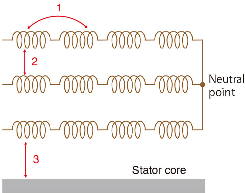
Partial discharges can occur in the following locations within a motor winding:
- 1.Turn-to-turn: discharges caused by voltage differences between adjacent turns within a single phase winding
- 2.Phase-to-phase: discharges caused by contact between wires belonging to different phases, or caused by misalignment or tearing of insulating paper
- 3.Phase-to-core: discharges resulting from contact between winding-wires and the stator core, or caused by misalignment or tearing of insulating paper.
Conventionally, quality assurance for inverter-driven motors in the production line has relied on a combination of insulation resistance tests, hipot tests, and surge tests to identify potential electrical deterioration. While hipot and surge tests effectively identify products with existing insulation breakdowns, they lack the sensitivity to detect latent defects that may not yet manifest as a complete failure. To address this limitation, the integration of partial discharge testing with high-precision detection capabilities is crucial. By proactively identifying potential defects through partial discharge detection before they progress to catastrophic insulation failures, these tests contribute significantly to enhancing the overall quality and reliability of inverter-driven motors.
Conclusion
In conclusion, while inverter-driven motors offer significant energy efficiency advantages, they can be susceptible to issues like partial discharges arising from the rapid switching inherent in their operation. To ensure the long-term reliability and safety of systems using inverter-driven motors, the implementation of rigorous partial discharge testing is essential. At HIOKI, we specialize in providing a comprehensive suite of solutions for both static and dynamic motor testing and measurement.
Check out our reading recommendations to learn more about our motor measurement solutions. If you want expert guidance and support for energy-efficient or other applications, please feel free to contact us.