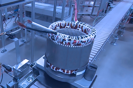
Detect Defects at an Early Inspection Stage of Motor Production Lines
Enables One-turn Shorts testing, Partial Discharges testing, and testing Coils after Rotor is Installed
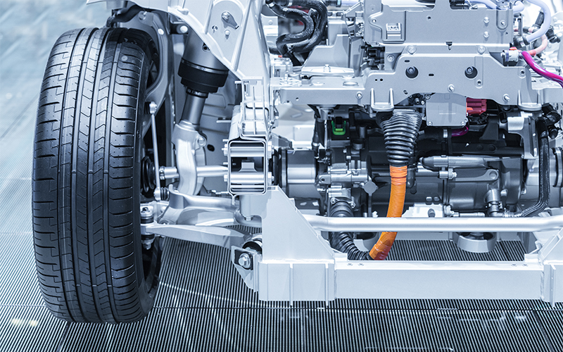
Demand for vehicle motors is rising as adoption of electric vehicles (EVs) grows. Vehicle motors, which closely affect driving performance and safety, must deliver high levels of performance, quality, and reliability.
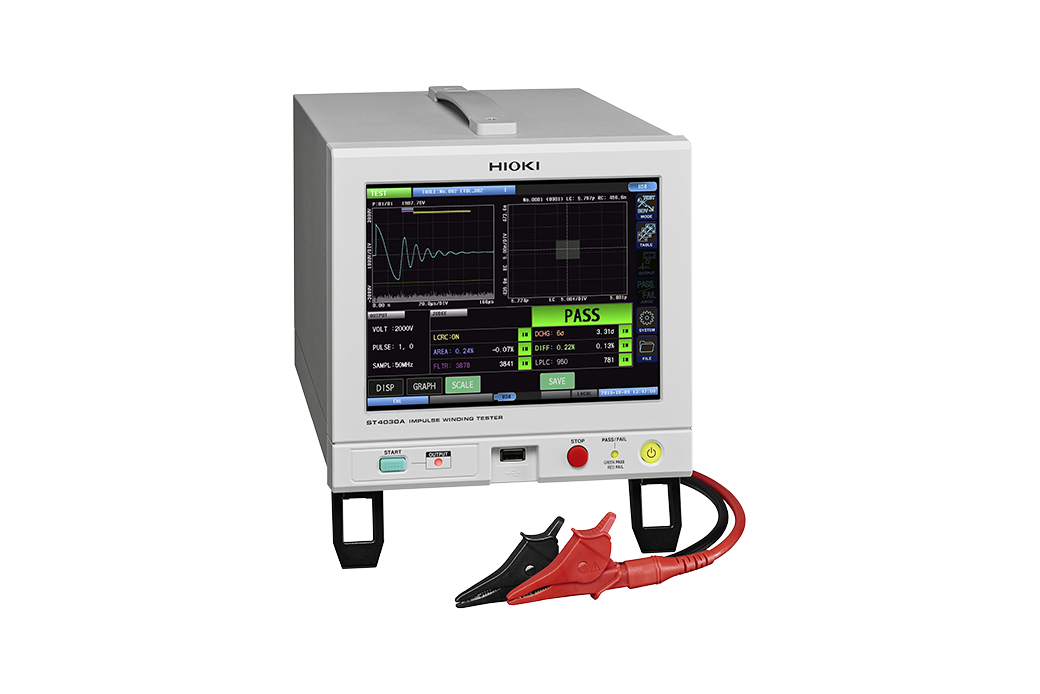
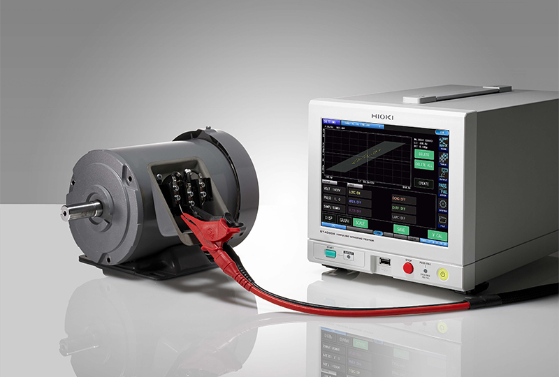
Hioki’s Impulse Winding Tester ST4030A can test windings under conditions that have been untestable until now, allowing operators to detect minuscule defects that have gone undetected in the past. Since it can detect defects earlier during testing processes on motor production lines, the ST4030A can eliminate the need to go back and repeat steps in the production process. As a result, it promises to make a significant contribution to saving man-hours and improving work efficiency.
 IMPULSE WINDING TESTER
Reliability requirements for windings: Growing more stringent year by year
It’s essential to maintain insulation performance between wires in windings, which are used in devices like motors and transformers. Inverters, which are generally used to drive the motors used in EVs, are evolving due to their use of semiconductors capable of accommodating higher voltages and higher-speed switching. Switching operation causes the voltage output by inverters to surge, resulting in the momentary application of a high voltage across the windings in the motor. This surge can cause a phenomenon known as partial discharge if there are any defects in the insulation, leading the insulation to corrode and degrade over time. The progression of such degradation can lead to short-circuits between winding wires and insulation breakdown, with potential effects including the risk not only of motor failure, but also of fire.
In recent years, adoption of EVs and advances in self-driving functionality have accelerated the pace of improvements in the performance of vehicle components. This process in turn has been pushing up reliability requirements for vehicle motor windings year by year. To prevent failures and serious accidents, it’s essential that even minuscule defects be detected during testing.
Impulse winding testers are used to test insulation performance in windings. These instruments apply an impulse voltage to both ends of a winding and detect the resulting voltage waveform (response waveform). They then generate pass/fail judgments by comparing the response waveform from the winding under test to the response waveform obtained from a known-good winding to check for any divergence. The instruments play an essential role in evaluating winding quality.
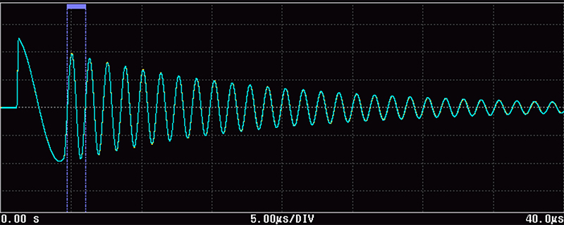 Response waveforms
Issues affecting conventional impulse winding testers
However, several issues affect motor winding testing carried out with conventional impulse winding testers.
- 1.Difficulty of detecting defective windings when the difference between the test and known-good response waveforms is small
- The conventional approach to comparing response waveforms is to compare the area of a specified interval of the waveforms and use that information to make a pass/fail judgment. When relying on this method of comparison, it becomes difficult to make pass/fail judgments if the area values differ only slightly, for example by several percentage points. As a result, it cannot be used to identify defects like one-turn shorts, which result in an extremely small difference between response waveforms.
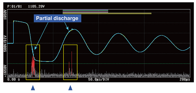
- 2.Difficulty of detecting minuscule partial discharges
- If a winding continues to be used while undergoing partial discharges, degradation of its insulation will progress, potentially leading to a short-circuit or insulation breakdown. Major problems can be prevented by detecting partial discharges early on. However, partial discharges involve extremely small discharges, and the difficulty of distinguishing the resulting small voltage difference from noise components makes it difficult to detect them.
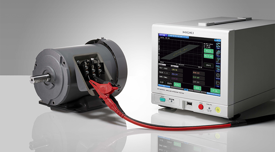
- 3.Instability of measured values when testing coils with attached rotors
- Company A, which develops and manufactures motors for use in machinery of all sizes, frequently found that motors whose coils exhibited no issues later proved to be defective once the manufacturing process was completed. When the company disassembled and tested the problematic motors, it found that their windings had sustained damage when the rotors were attached to the stators, resulting in insulation defects. When coils are tested with an impulse winding tester after rotor installation, the stray capacitance between the rotor and stator varies with the position at which the rotor is installed, causing the detected response waveforms to vary. As a result, the conventional method of comparing the area of response waveforms is incapable of accurate measurement due to variability in test results.
By quantifying the response waveform, it is possible to inspect the coil in the rotor installed state and the inspection to detect the defect of one turn shorts.
The ST4030A resolves every issue with conventional testers.
- 1.Generating clear thresholds for pass/fail judgment by quantifying response waveforms
- In addition to conventional comparison of waveform area, the ST4030A generates judgments by comparing LC and RC values. These values are obtained by quantifying the impulse winding tester’s response waveforms (during layer short testing). When the two values are mapped on a two-dimensional plane, their distributions show a clear difference between non-defective and defective parts. In this way, quantifying response waveforms and evaluating them in a quantitative manner makes it possible to detect defects like one-turn shorts that are difficult to identify through area comparison due to the minuscule differences they cause.
- *Depends on measurement conditions
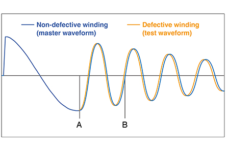 Area comparison based on waveforms
Pass/fail judgments are difficult when area differences do not exceed several percentage points.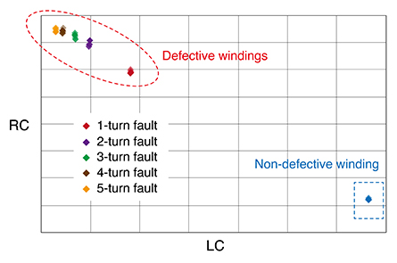 Quantification of response waveforms
The distributions of values differ for defec-tive and non-defective windings
- 2.Using a proprietary Hioki filter to reject noise components and extract partial discharges
- Discharges require high-precision detection performance due to their small voltage differences and high frequencies. Thanks to its 200 MHz sampling frequency and 12-bit sampling resolution, which allow high-speed, high-precision waveform detection, the ST4030A can precisely detect extremely weak partial discharges that would otherwise be obscured by noise. The optional Discharge Detection Upgrade ST9000, which includes a proprietary Hioki filter, can be used to reject noise components from high-frequency components in response waveforms so that the partial discharge component alone can be extracted and used to make judgments. The ST9000 makes it easy to detect partial discharges without the need for separate peripheral equipment like a discharge detection antenna, allowing problems to be resolved early on as part of a predictive maintenance regime. It’s essential to detect partial discharges, which can occur as wire insulation gradually corrodes and leads to insulation degradation, in vehicle motors, which must operate safely over the long term. The ST4030A reliably allows defective components to be rejected.
 Isolation of noise components
High-frequency discharge compo-nents are isolated by a proprietary Hioki filtering process.
- 3.Testing coils after rotor installation
- The ST4030A can make pass/fail judgments based on differences in the distribution of LC and RC values, which are obtained by quantifying response waveforms. Since the distribution of values varies for non-defective and defective parts even if the response waveforms change, testing can be carried out after rotor installation by creating non-defective and defective part judgment areas. This approach makes it possible to detect defects during the rotor installation process, reducing man-hours that would otherwise be spent on sending motors found to be defective after completion back to the previous step in the production process for additional testing and reassembly.
When it used a demonstration ST4030A unit to test coils after rotor installation, Company A verified that the instrument was able to make measurements in a stable manner. After finding that it could detect single-turn layer shorts based on LC and RC values, the company purchased the instrument in order to boost the detection rate for process defects.
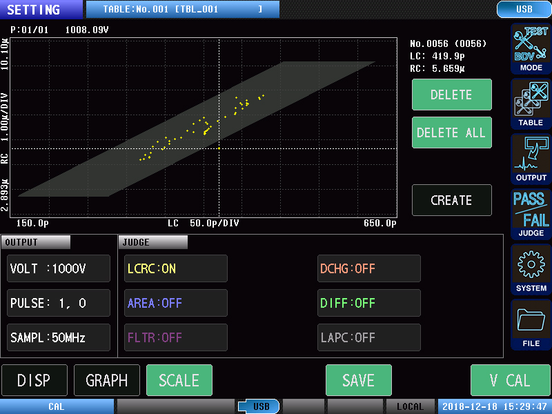 Distribution of LC and RC values when the rotor is rotated
When LC and RC values are sampled while rotating the rotor, the distribution for defective phases differs from the distribution for healthy phases.
High-reliability measurement data
The ST4030A provides the high performance needed to resolve customers’ issues in other areas, too.
For example, it delivers high measurement stability thanks to low variability in applied voltage values. Since measured values obtained while testing the same workpieces vary little from instrument to instrument, the known-good waveform data that serves as reference data can continue to be used even when an instrument is replaced. Moreover, reliability is guaranteed since voltage detection accuracy is defined under the accuracy guarantee conditions. In addition, the ST4030A is capable of even more reliable testing since it can carry out tests that comply with IEC standards.
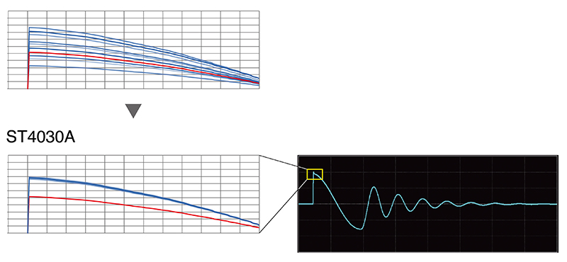 Applied voltage variability
Upper waveform: Variability in waveforms makes it difficult to detect shorts.
Lower waveform: Low waveform variability allows defective windings to be detected with a high degree of precision
For example, Company B deployed multiple instruments at its plant as part of a series of steps boosting production volume after using demonstration units to measure coils and verifying stable, problem-free measurement. The company is using known-good waveform data in testing without worrying about measured-value variability from instrument to instrument. Stable measurement allows testing with even more stringent judgment standards using LC and RC values, prompting the company to start quantifying response waveforms in its testing. Finally, the instrument's touch panel-based controls make it easy for users who are unfamiliar with instrument operation to use the product, facilitating a smooth transition process when replacing instruments. Manufacturing departments have praised the ST4030A’s functionality for saving measurement screens as BMP files. Development departments have praised the instrument's insulation breakdown voltage (BDV) test function.
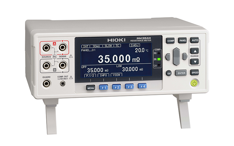
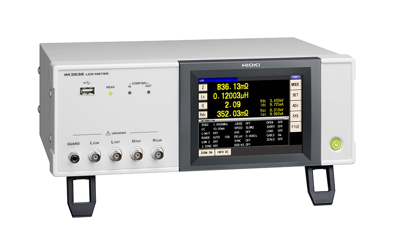
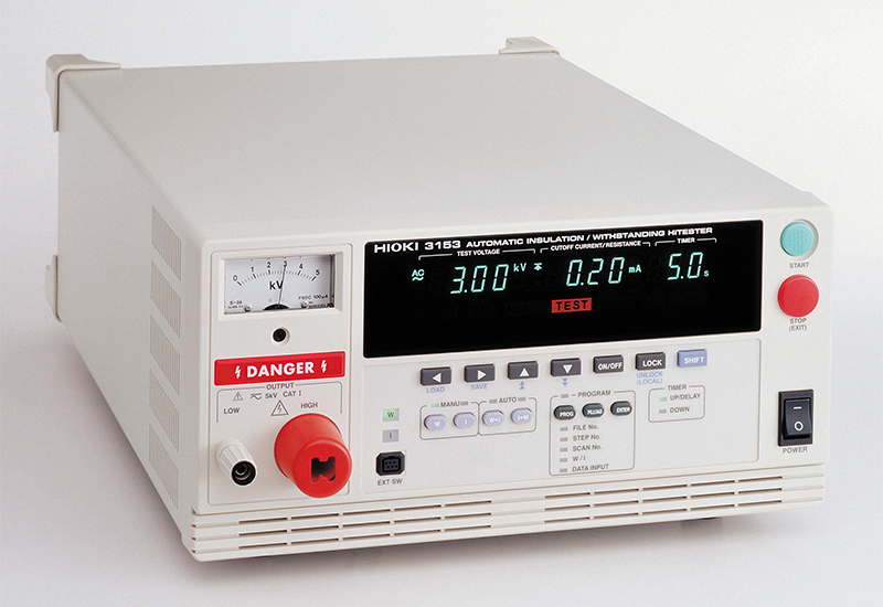
Hioki offers a range of motor-related measuring instruments, including resistance meters, LCR meters, and withstand voltage testers. Positive feedback from manufacturing and development departments is lending momentum to efforts to standardize on particular instrument manufacturers.
Accommodating future voltages increases
Electrification of EVs and other means of transportation is proceeding. Generation of electricity using renewable energy sources is also growing more common from the standpoint of carbon neutrality. With each passing year, the output and drive voltages used by motors and generators in these applications are growing.
Higher drive voltages mean higher test voltages. Instruments must accommodate these changes. Hioki will work to improve the performance of its impulse winding testers so that they can accommodate even higher voltages in the future. We will also add new functionality and improve existing functionality as we assess current conditions and anticipate future developments.
Hioki offers a broad range of measuring instruments with functionality engineered to meet customers’ demands. Demonstration instruments are available, so please contact Hioki if you wish to experience the functionality of our products for yourself. We’re also happy to provide samples so that prospective customers can conduct measurement tests. And please get in touch with any measurement issues you’d like to resolve or instruments in which you're interested.