Power Measurement Method for Multiphase Motors
Introduction
As the performance of EVs and industrial equipment continues to improve, trends toward multiphase motors are accelerating. There is an increasing number of cases where multiphase motors, such as 5-phase and 6-phase configurations, are being adopted instead of the traditionally mainstream 3-phase configuration. Specific applications include electric aircraft and autonomous EVs.
By adopting multi-phasing, the current capacity of each phase can be reduced, leading to decreased resistive losses and reduced heat generation. As a result, it becomes possible to achieve higher output and improved efficiency in motors, as well as other benefits such as increased redundancy*1 and output density. On the other hand, the added phases make measurement and evaluation significantly more difficult, posing the challenge that this application note aims to address.

- *1:Due to the presence of multiple independent windings, if one phase fails, the remaining phases can continue to operate while maintaining a certain level of torque.
Challenges and Key Points in Power Measurement of Multiphase Motors
There are two main challenges in the power measurement of multiphase motors:
Increase in Voltage and Current Channels
Since current and voltage must be simultaneously measured—one input power channel for each phase—more power measurement channels are needed for these multiphase configurations. For example, a 5-phase motor, requires 5 dedicated power channels for voltage and current (6 channels for a 6-phase). This is problematic because measurement systems with a higher number of channels traditionally have lower accuracy. One must especially be diligent in ensuring their measurement system has high accuracy in the high-frequency range. This is because the phase errors of the voltage and current of each phase directly affect the calculation of active power and efficiency, making phase accuracy as important as bandwidth characteristics.
Complexity of Computational Processing
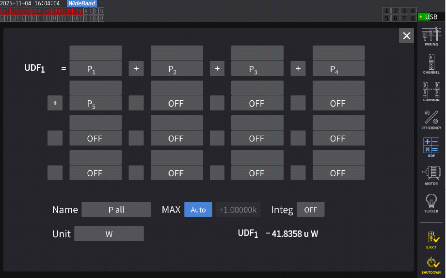
In three-phase systems, standardized formulas are generally used for calculating active power and efficiency. However, since those formulas are based on phase-angles , they do not apply in 5- and 6-phase systems . As a result, each phase’s power must be calculated individually and then summed. The PW8001’s User Defined Function*2 is perfect for such customizable power measurement calculation of multiphase motors.
- *2: This is a feature that allows users to set their own calculation formulas and display the calculated values in real-time on the measurement screen.
Recommended Measurement Instrument for Power Measurement of Multiphase Motors
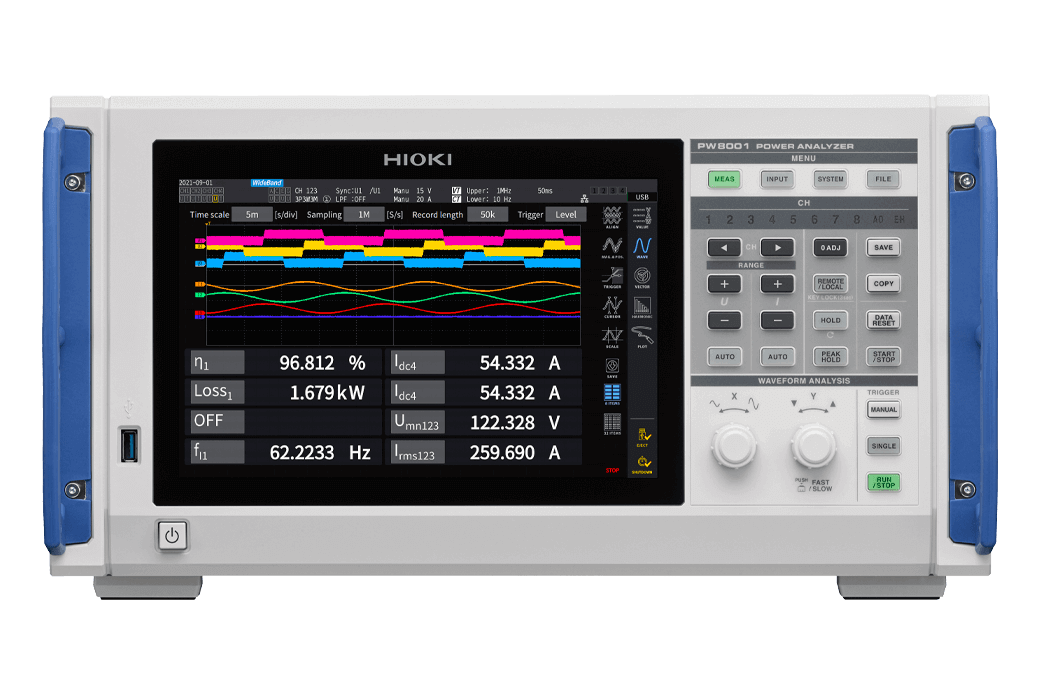
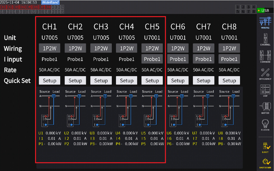
The PW8001 is recommended for multiphase motor power measurement. It guarantees high amplitude accuracy and phase accuracy over a wide bandwidth. On its large screen, you can check the real-time power parameters of each phase on the waveform screen or intuitively check the phase balance on the vector screen. By ordering the motor analysis custom option at the time of purchase, you can measure efficiency and losses of the motor in addition to the standard torque and rotation. As an added benefit of Hioki’s specialty in the current sensor and power analyzer combination, current sensors that acutely match the rated current and diameter of the measurement targets can be chosen from Hioki’s extensive lineup.
Measurement Method
Here, using the PW8001, we will introduce specific steps for measuring the power of multiphase motors.
Basic Considerations for N-Phase Motor Power Measurement
Voltage: measure between each phase and the neutral point or the motor chassis (or ground line).
Current: measure the line current for each phase.
Number of Channels (hereinafter “channel number” abbreviated as “CH”): prepare the same number of channels as the number of phases in the motor.
For both delta and star connections, all voltage measurements use the motor chassis (or ground line) as the reference. In the case of a star connection, ideally, the neutral point should be used as a reference, but since extracting the neutral point is often difficult, the motor chassis or ground line is typically used as a reference.
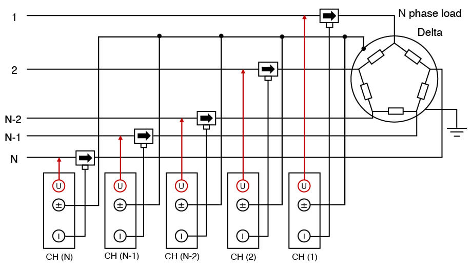 Delta connection
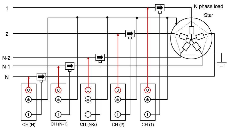 Star connection
With this reference, the active power of an N-phase motor is given by the following equation.
Pall= P1+P2+⋯+PN-2+PN-1+PN
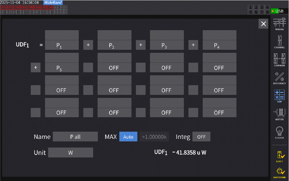
Example 1: 5-Phase Motor
For a 5-phase motor, a 1P2W connection is used with the motor chassis (or ground line) as the reference.
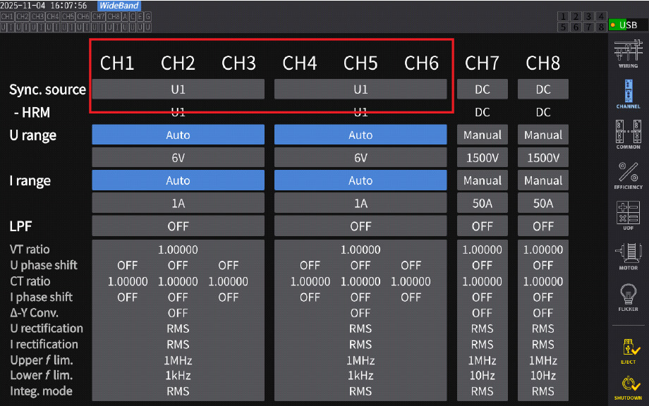
In the wiring settings screen, configure each channel as 1P2W (for an N-phase motor, N channels configured as 1P2W).
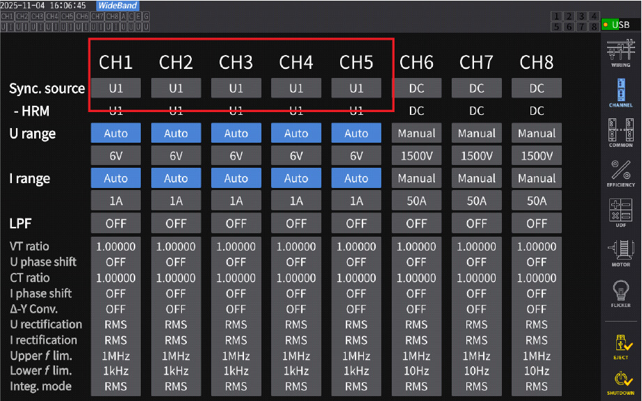
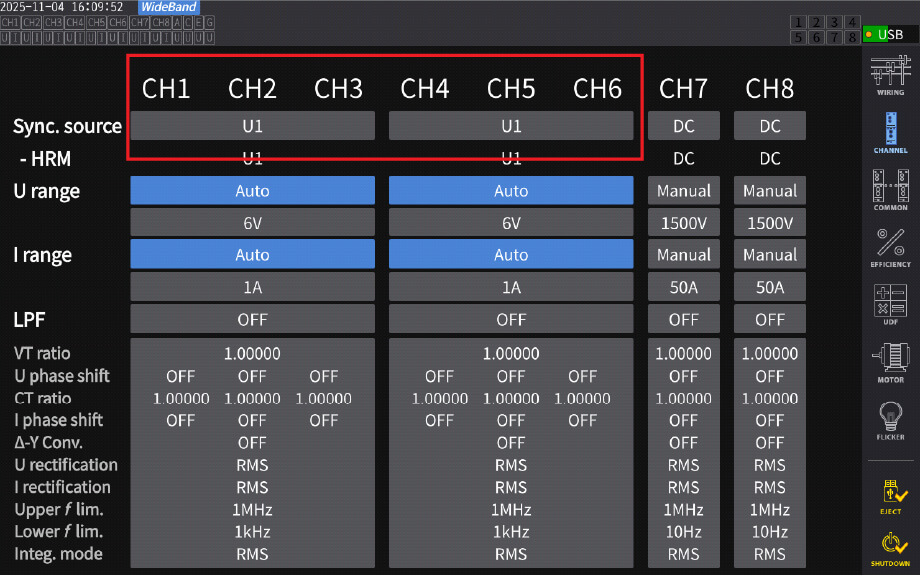
Set the sync source for all 5-phase channels to the same signal (e.g., CH1 voltage).
Use UDF to calculate and display total power as the sum of all phase powers (e.g., P1+P2+P3+P4+P5 ).
In other words, for an N-phase motor, all N phases are summed.
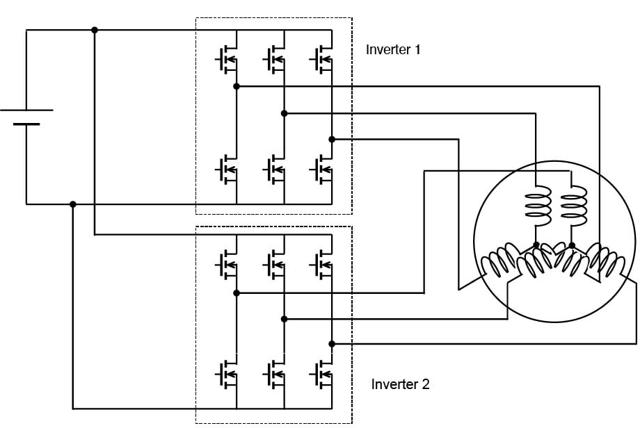
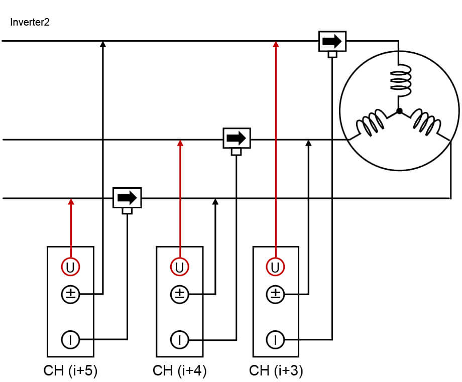
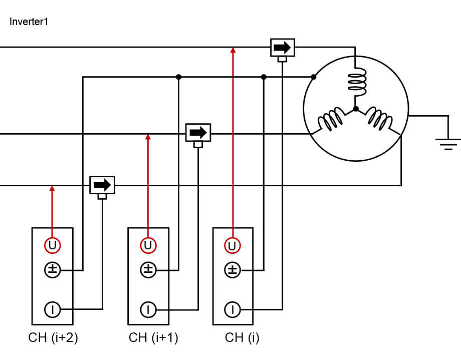
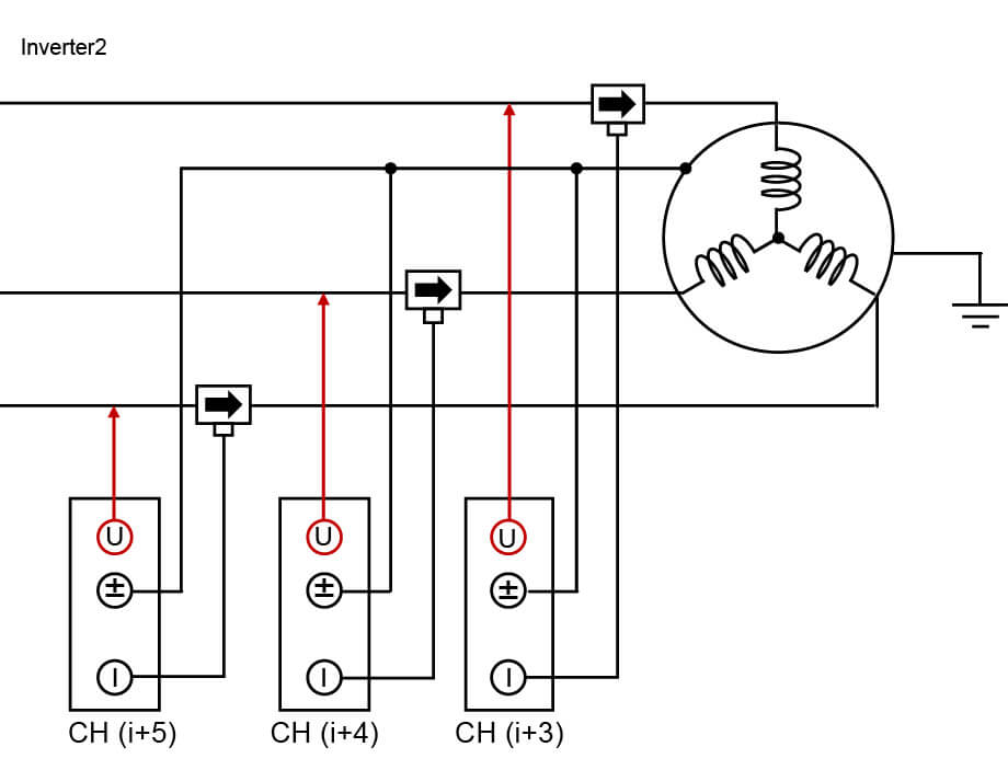
Example 2: Active Power of an Open-End Winding Motor (6-Phase Dual-Inverter)
The total active power of an open-end winding motor is the sum of the power from the inverter (Inverter 1) and secondary inverter (Inverter 2):
Pall= Pprimary+Psecondary
where Pprimary is measured on CH1–CH3 and Psecondary on CH4–CH6.
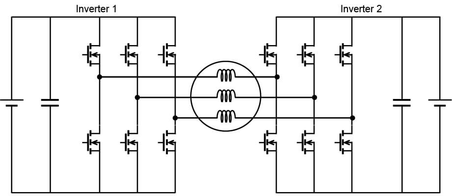
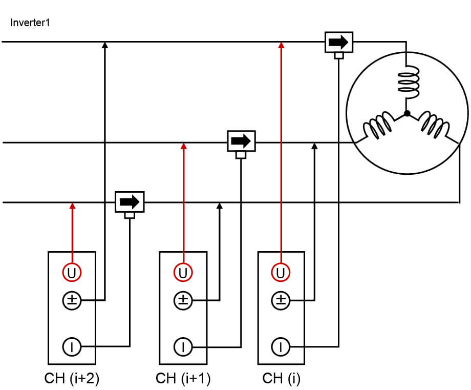
As shown below, measure phase voltage on the primary and secondary sides using the ground line as reference. Orient current sensors so that the current direction arrow on each sensor points from inverter to motor (ensuring positive current measurement—see diagram).
Since the battery negative is typically isolated from ground, use a common reference (e.g., Inverter 1 frame ground) for all channels to avoid ground potential differences.
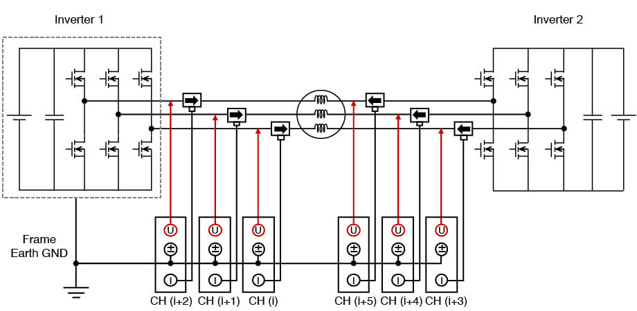
Use Inverter 1 frame ground as the common reference. In the wiring settings configure CH1–CH3 (primary) and CH4–CH6 (secondary) as 3P4W.
Set the sync source for all channels to the primary-side voltage (Inverter 1).
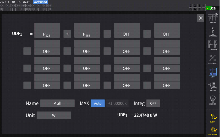
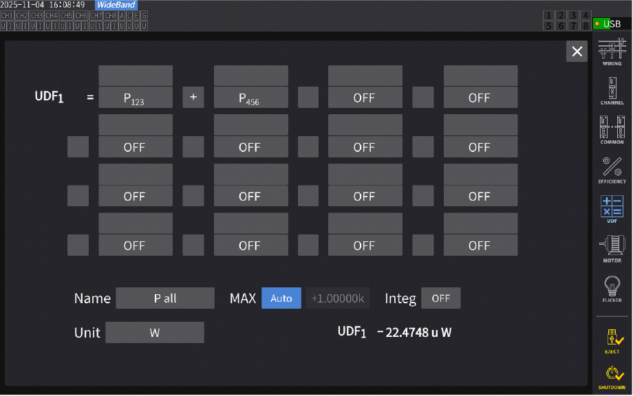
In UDF, enter:
Pall = P123 + P456
(where P123 = CH1–CH3 power, P456 = CH4–CH6 power—see right).
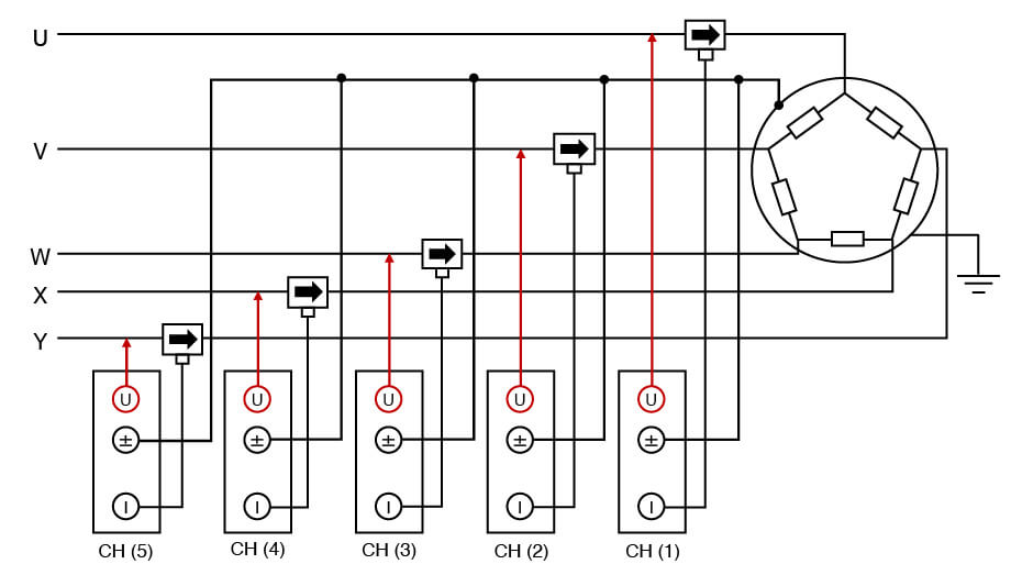
Example 3: Active Power of a Double Three-Phase Motor
The total active power of a double three-phase motor is the sum of power from two 3-phase systems:
Pall=P(sys1)+P(sys2)
(where sys1 = CH1–CH3, Sys2 = CH4–CH6—see diagram)
Measure each 3-phase system independently:
System 1: Inverter 1 + motor set 1 (CH1–CH3)
System 2: Inverter 2 + motor set 2 (CH4–CH6)
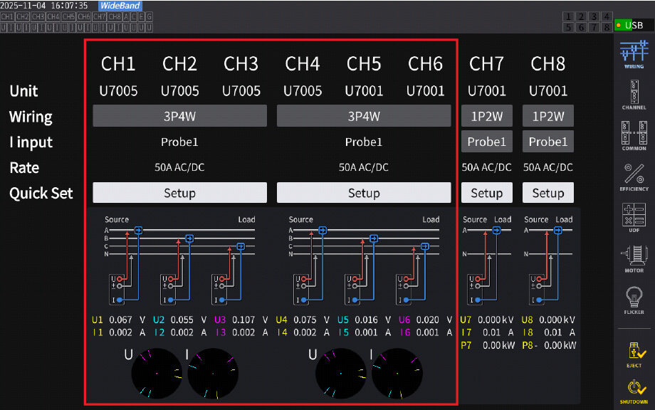
・ Wiring and Wiring Screen for 3P3W3M
The wiring and wiring settings are done as shown below.
In the diagram, the first system is set to CH1 to CH3, and the second system is set to CH4 to CH6.
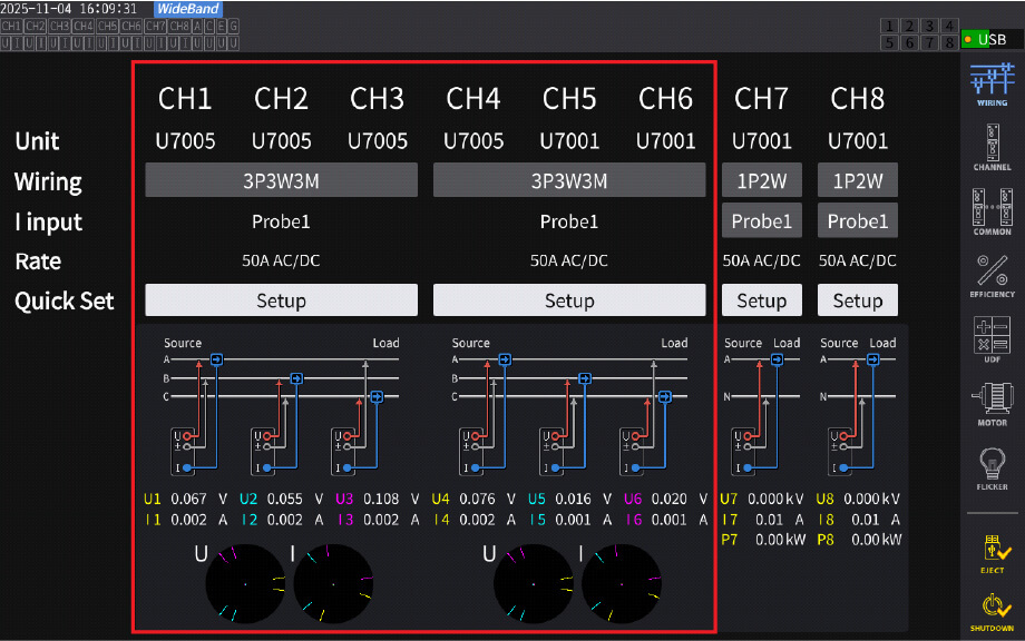
・3P4W Wiring (Per System)
Use the motor chassis (or ground line) as the common reference—the neutral point is ideal but typically inaccessible.
Channel Assignment:
System 1: CH1–CH3
System 2: CH4–CH6

Sync & Total Power:
Set the sync source for all channels to System 1 voltage (e.g., CH1).
In UDF, enter: Pall= P123 + P456
Using the UDF function, the total power is calculated as shown: Pall = P123 + P456
Conclusion
With the advancement of motor technology, the adoption of multiphase motors, including five-phase and six-phase configurations, is expected to increase further in the future. The methods introduced in this application note enable accurate power measurement even in multiphase configurations, allowing for high-precision evaluation of the power characteristics of multiphase motors, as well as more reliable performance analysis and efficiency improvements during the development stage.
For more detailed information about the PW8001, please visit Hioki's product page. If you have any questions regarding the application note or measurements, please feel free to contact us.