How to Measure Insulation Resistance
Overview
Electrical insulation materials are critical in electrical systems in terms of both safety and performance. For maintenance of motors, transformers, switch gears, etc., insulation resistance inspections are performed on a regular basis to check if insulators function as expected. In R&D, an insulation resistance test is also carried out for the characterization of materials’ electrical properties.
This article discusses the fundamentals of the insulation resistance test.
How insulation resistance testing equipment works
Super Megohmmeters (also known as electrometers or picoammeters) and handheld insulation testers are often used to test the resistance properties of electrical insulation (i.e. insulation resistance test). These testing equipment all apply a set DC voltage to the device under test (DUT). They then measure the current of the DC voltage flowing through the DUT. The constant DC voltage and the measured current allows the meter to calculate the resistance using Ohm’s Law. Since high resistance of a few gigaohms [GΩ] results in minuscule current, these devices which measure electrical insulators must be equipped with accurate ammeters.
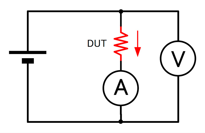 Overview of a circuit diagram for insulation resistance measuring equipment
For maintenance testing of insulation systems, we must make sure that the insulation is able to resist more than the system’s maximum voltage. That is why the voltage applied by the testers to perform these tests are typically higher than the equipment’s voltage.
Unlike maintenance testing, identifying the electric characterization of insulation material requires measurement instruments with much more precision. Since the values are so precise, changing seemingly innocuous conditions can change the measurement values. That is why it’s important to measure different materials under as similar conditions as possible and then compare the values. Examples of such conditions that must remain the same (or as close as possible) are temperature, humidity, sample-size, and type of measurement electrode. Furthermore, measurement instruments used for characterization tests must be able to measure higher resistance than maintenance testers. That is why these devices must contain ammeters that are able to accurately measure very small current.
Mystery of the value-drift
During resistance testing, we often see the measured values drift. This may cause the engineer to doubt the accuracy of the measurement instrument, however this is actually an unavoidable phenomenon with a reason behind it. Fundamentally, the phenomenon is caused by change in the measured current over time due to dielectric polarization.
To see why the current changes, it’s convenient to express an insulation material as an equivalent circuit of multiple capacitors and resistors connected in parallel and in series.
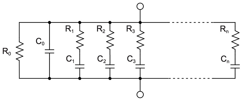
This equivalency causes the material to go through three states: the electrification state, polarization state, and steady state.
- 1.Electrification state: This state occurs in an instant. It represents the moment the voltage is applied and a large amount of current flows through the DUT, as if there was a short-circuit through C0 (see figure “Equivalent circuit of insulation materials” above).
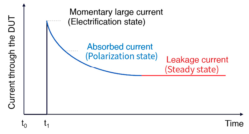
- 2.Polarization state: This state is akin to the capacitor component being charged. Much like a capacitor, the material starts to polarize. As it polarizes and charges (charge from C1 to Cn), less and less current flows. This phenomenon is also called “current absorption” since it is as if current is being absorbed by the capacitive components.
- 3.Steady state: The material enters this state at the moment the capacitor in the equivalent circuit finishes polarizing or charging. Once the capacitive components finish charging, no more current flows through it. At this point, since the capacitive components do not allow current to flow, all that is left is the high resistance of the resistive component (R0 ). This results in a steady amount of leakage current to flow.
The graph below shows the current that flows through the DUT after voltage application starts at t1. The time it takes until the material enters the steady state depends on the material being tested—it may take several hours to even several days. To practically compare measurements, the 1-minute value is commonly used. This is the value 60 seconds after the voltage is first applied.
How to test insulation resistance
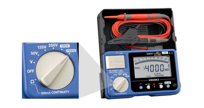
Handheld insulation testers
Handheld insulation testers have functions that make field maintenance easier. By simply plugging in test leads and setting the test voltage, you are ready to test. (Typically, the tester must apply a voltage that is higher than the operation voltage of the DUT.) After the voltage is set, the user need only press the measurement-start key. Some testers have a setting to measure the 1-minute value.
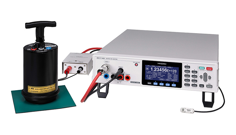
Bench-top insulation testers (Super Megohmmeters or electrometers)
In R&D, various kinds of materials are tested with a Super Megohmmeter. The measurement electrode must match the material’s shape or size. Most equipment allow you to select the test voltage. Test-time can be configured in detail (e.g., setting the charge time). Sometimes dedicated software applications are available. They often allow you to start measurement through the app instead of with the measurement’s start button.
Summary
Electrical insulation materials in devices like motors and transformers require regular insulation resistance tests because these materials keep equipment safe and performing at their best. Both Super Megohmmeters and handheld insulation testers apply DC voltage to measure currents and calculate resistance. Handheld testers, with their easy operation, are ideal for field use, while benchtop testers like the Super Megohmmeter offer high precision and a range of settings and electrodes for detailed testing of various materials.
To understand more about resistivity and resistance measurement, check out our reading recommendations below.