A data logger that can interoperate with an HIL simulation system thanks to high-speed, real-time data output
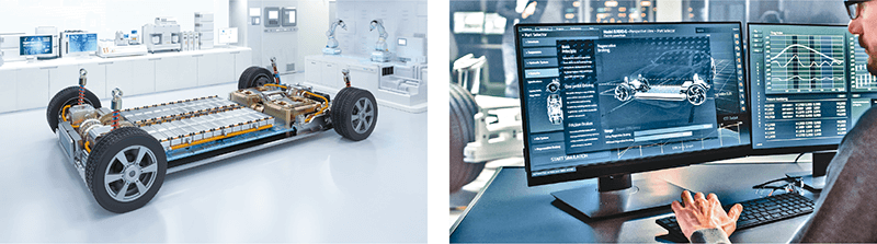
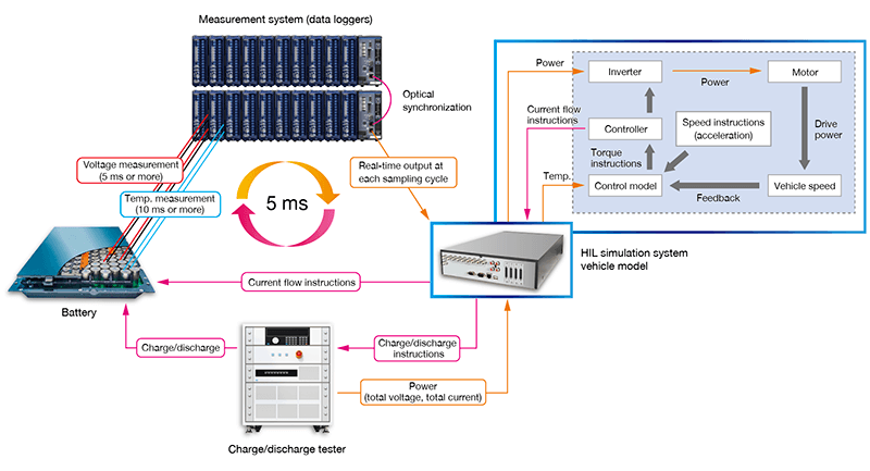
Hardware-in-the-loop (HIL) simulation systems are used during the verification stage of electric vehicle (EV) development. Advanced verification processes of battery packs combine actual batteries with simulation technology. These tests are done in situations such as verifying/monitoring individual cells in the battery pack without a battery management system (BMS) or verifying charge/discharge control while simulating an EV driving environment. Such verification setups require measurement data of specifying individual cells’ voltage and temperature to be sent in real time to the simulation system.
This article introduces an example of such a setup in which a data logger is used to measure the voltage and temperature of individual battery cells and send the acquired data to a HIL simulation system.
Data logger performance required for this type of measurement
To assess voltage variations at a suitable level of detail while battery cells are charging or discharging, an instrument must be controlled and data captured on a short, millisecond-order cycle. In control simulations using HIL systems, which demand a real-time data feed, the measuring instrument used must be able to transfer an enormous quantity of cell measurement data to the system at high speeds. As a result, the data logger must posses a level of performance that lets it output data for a large number of channels measured via high-speed sampling with low latency. Moreover, when measuring a high-voltage battery pack, it’s essential for the instrument to provide sufficient insulation performance so that the test can be carried out safely.
Data loggers used for this type of measurement must deliver the following three types of performance:
· The ability to output data measured via high-speed sampling in real time
· A high level of insulation performance
· Enough channels to measure a high-voltage battery
An optimal data logger for interoperating with a HIL simulation system
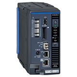
Hioki’s Data Logger LR8102 is ideal for use in control simulations that involve charging and discharging an actual battery. The measurement system described in this application note combines the LR8102 logger with the Voltage/Temp Module M7100. The system measures the voltage or temperature at each battery cell and outputs the measured data to the real-time simulation system at high speed. (The sampling speed is limited by the parameters being measured and number of channels being used per module.)
Data Logger LR8102
· Connect up to 10 measurement modules to 1 logger
· Synchronize up to 10 data loggers
· High-speed data transfer (UDP)
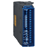
Voltage/Temp Module M7100
Input: 15 ch (voltage/temperature)
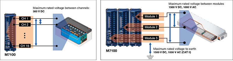
Insulation performance between channels: 300 V DC
Insulation performance between terminals and earth: 1500 V DC, 1000 V AC (CAT II)
Insulation performance between modules: 1500 V DC, 1000 V AC
Sampling speed (data refresh interval)
5 ms* (when using 1 ch to 8 ch), 10 ms to 10 s (when using 9 ch to 15 ch)
There are three reasons why the Data Logger LR8102 and the Voltage/Temp Module M7100 are ideal for interoperation with HIL simulation systems.
1. Realtime data output marching in step with high-speed sampling: UDP & 5 ms
The LR8102 can output data for an enormous number of cells in real time after each sampling cycle thanks to its use of the User Datagram Protocol (UDP).
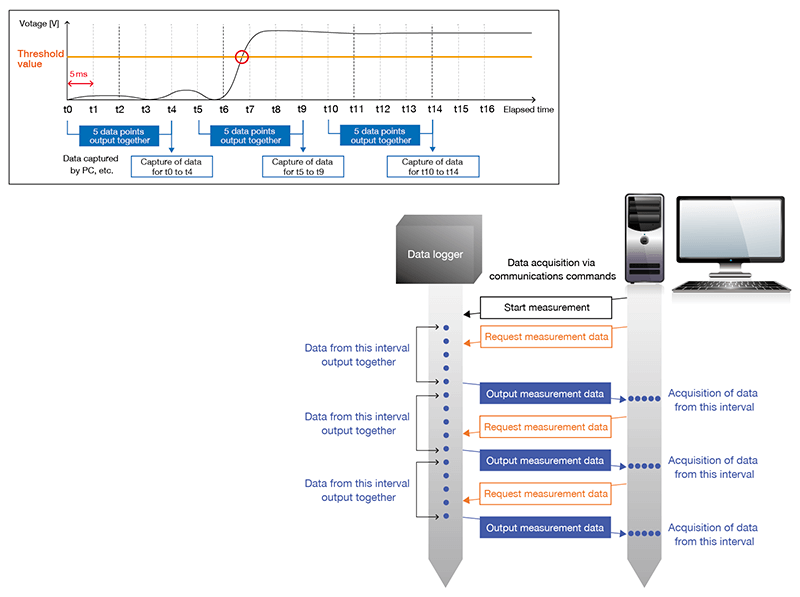
Typical data logger measurement and data output timing
Typically, communications commands are used to transfer data acquired by data loggers to upstream systems. It takes anywhere from tens to hundreds of milliseconds to acquire each data point. The speed at which data is transferred to the system isn’t always as fast as the actual measurement speed (millisecond order). Figure 1 illustrates measurement and data output timing for a typical data logger. Although the voltage value exceeds the threshold by t7, that data cannot be acquired until t9. In addition, in order for the upstream system to acquire millisecond-order measurement data without missing any data points, multiple data points must be acquired at once. However, HIL simulations systems, which acquire data in real time and provide feedback in the form of calculation results, can only use the most recent data, even if they acquire a block of data that contains multiple data points.
Figure 1
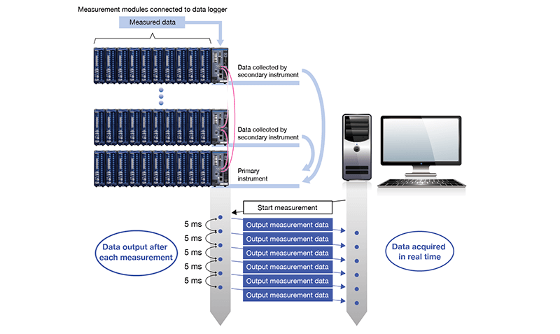
High-speed, real-time data output using the Hioki Data Logger LR8102
The Data Logger LR8102 can output measurement data in real time at each sampling cycle using UDP. Data measured by each module is collected by the data logger, which is connected to its modules via a newly designed, high-speed differential communications architecture. Data is transferred from secondary data loggers to the primary data logger via high-speed communications over optical fiber connections. All measurement data is aggregated by the primary data logger within 5 ms. Aggregated data is then output from the instrument's LAN port by its real-time OS. Low-latency acquisition of measurement data is accomplished by harnessing a hardware architecture with sufficient bandwidth and real-time processing capability to handle tasks from measurement to output. By outputting data from the data logger to the system at high speed in real time using UDP, measured data can be fed to the HIL simulation system's control loop.
The graph shown in Figure 2 presents the results for a verification test of the LR8102’s UPD output communications cycle. In the test, measurement data was output via UPD every 5 ms, and the delay was observed. The results were extremely stable, indicating a communications cycle of 5 ms ±600 μs, even when the plot was repeated more than 140,000 times. Thanks to the high stability of this cycle, the simulation system can acquire stable measurement data, even when it’s output at high speed. (The graph depicts the results of receiving 1 packet via a switching hub.)

Figure 2. The LR8102’s UPD output communications cycle
2. High insulation performance: 1500 V DC CAT II
High insulation performance is essential in order to safely measure cell voltages in a high-voltage battery pack. For example, in order to measure cell voltages in a battery pack with a total voltage of 800 V, you would need an instrument with a module-to-module voltage of 800 V and a terminal-to-earth voltage of 800 V. Thanks to 1500 V DC CAT II insulation performance that’s compliant with the EN IEC 61010 safety standard, the Voltage/Temp Module M7100 can safely measure high-voltage systems.
3. Enough channels to measure a high-voltage battery: 800 channels (at 5 ms sampling)
Measuring cell voltage and temperature in a high-voltage battery pack means measuring a large number of channels. For example, if using a cell voltage of 4 V, a total of 200 cells would be needed to build a battery pack with a total voltage of 800 V. To measure the voltage and temperature of all cells in that battery pack, you’d need an instrument with 400 channels. In EV development, batteries in excess of 1000 V are being prototyped as part of testing, and it’s likely that instruments will need to have even more channels in the future.
The Data Logger LR8102 can be combined with measurement modules to freely expand the number of input channels. As shown in Figure 3, 10 LR8102 data loggers, each connected to 10 M7100 modules, can be connected with optical connection cables to create a system that can achieve synchronized sampling of up to 800 channels at a sampling rate of 5 ms. Data measured by the M7100 modules is collected by the LR8102 to which they are connected, and all data is aggregated by the primary logger within 5 ms. Aggregated data is then output from the primary logger's LAN2 port, which is used exclusively for data output, at high speed and in real time.
Note: The 5 ms sampling speed is supported when a single M7100 uses no more than 8 channels, all of which are being used with a voltage range. Temperature measurement is supported starting at a sampling speed of 10 ms.
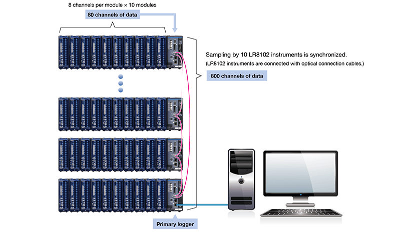
Figure 3
Example system
This section introduces an example system for using the maximum number of LR8102 Data Loggers and M7100 Voltage/Temp Modules. Up to 10 LR8102 Data Loggers can be synchronized. A system that uses up to 100 M7100 modules can be created by connecting 10 M7100 modules to each LR8102. The parameters measured by the M7100 modules can be mixed and matched as desired. In this example, 70 of the 100 M7100 modules are being used for voltage measurement, while the remaining 30 modules are being used for temperature measurement.
As shown in Figure 4, the 10 LR8102 Data Loggers are connected with optical connection cables to allow synchronized sampling. Each LR8102 is connected to 10 M7100 Voltage/Temp Modules. This measurement system can measure voltage (560 channels at 5 ms sampling) and temperature (450 channels at 10 ms sampling) at once. All data is aggregated by the primary logger within 5 ms and output at high speed and in real time from its LAN2 port, which is used exclusively for data output. In this way, LR8102 Data Loggers and measurement modules can be combined to create multichannel measurement systems that can interoperate with HIL simulation systems in charge/discharge testing of 1500 V large-scale battery systems.
Note: The 5 ms sampling speed is supported when a single M7100 uses no more than 8 channels, all of which are being used with a voltage range. Temperature measurement is supported starting at a sampling speed of 10 ms.
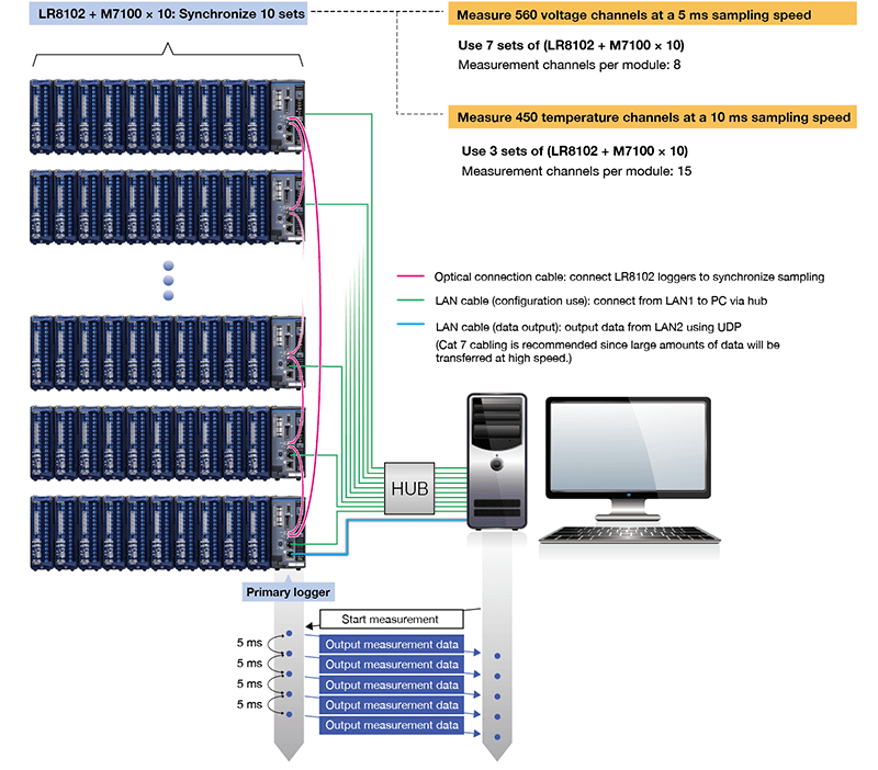
Figure 4
Summary
When embedding a data logger in a control simulation system that demands real-time performance, like a HIL system, the logger’s sampling speed and data output speed are extremely important considerations. In addition, any instrument used to measure high-voltage battery packs will need to be capable of multichannel measurement while also providing high insulation performance. A system that combines Hioki’s Data Logger LR8102 and M7100 measurement modules can safely and accurately acquire data at a maximum sampling speed of 5 ms and output that data in real time output. Such setups support smooth interoperation with HIL simulation systems and promise to contribute to EV development. The DVD included with the product comes with a sample program for the system receiving data. This sample program can be used to receive LR8102 measured values using UDP, convert output formats into physical properties, and save the results in a file, allowing you to immediately try UDP operation for yourself.
Please visit Hioki's website for more information about these products.
Requests for demonstration units and questions about measurement should be directed to your closest Hioki representative through our contact form.