Measurement of the Conversion Efficiency of High-voltage, High-current Solar Inverters
Delivering high, R&D-level accuracy in a small, lightweight, and portable package

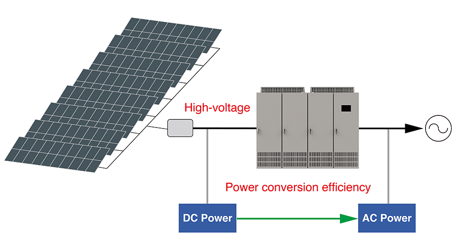
Power generation systems that use natural energy, for example solar and wind power installations, utilize solar inverters (or PV inverters) to convert the DC electricity they generate into AC electricity that can be used by households and other power grid customers. Engineers have been developing solar inverters that handle higher voltages and larger currents because photovoltaic systems that operate at higher voltages can function more efficiently thanks to lower power losses. These developments demand measuring instruments that can accommodate higher voltages and larger currents.
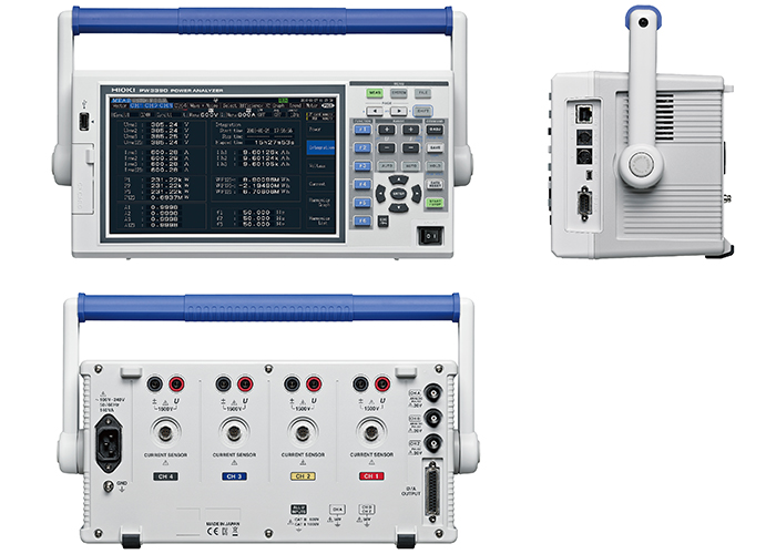
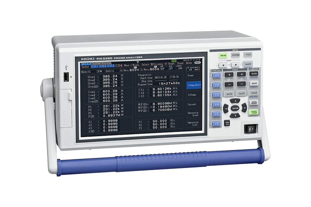
The Power Analyzer PW3390 can measure power in solar inverters that operate at 1500 V, which have recently entered into common use. The instrument performs on par with instruments that deliver the high accuracy required in R&D work despite its small, lightweight, and readily portable design.
Three issues affecting measurement of photovoltaic systems
Company A, a manufacturer of solar inverters, was dealing with a number of issues involving the power analyzers it used to measure high voltages and large currents.
Issue 1: The instruments couldn’t accommodate high voltages or large currents.
Evaluating the power conversion efficiency of high-voltage solar inverters requires current sensors and power analyzers capable of accommodating DC voltages of 1500 V and currents of several thousand amps on the input side. However, existing power analyzers were only able to accommodate 600 V or 1000 V. Calculating the power conversion efficiency of a solar inverter (or PV inverter) capable of operating at 1500 V required either first attenuating the voltage using high-voltage differential probes or a voltage transformer and then inputting those signals to a power analyzer for measurement, or checking the meters installed on the solar inverter itself.
As a result, it needed to measure power conversion efficiency accurately using a power analyzer that can accept high voltages and large currents.
Issue 2: There’s a difference in accuracy between instruments used in R&D and those used at manufacturing sites.
Solar inverters (or PV inverters) convert power generated by solar panels to grid AC power, and their performance is evaluated in terms of conversion efficiency. Currently, solar inverters (or PV inverters) deliver a high level of power conversion efficiency that ranges from 95% to 98%. As a result, Company A needs to accurately measure the power conversion efficiency of solar inverters (or PV inverters) that handle high voltages and large currents in its R&D facilities. The company also wants to assure quality on the production lines where the products it develops are manufactured in volume by measuring power conversion efficiency at the same, high level of accuracy as during the R&D stage.
However, typical power analyzers are large and difficult to move. They’re also expensive, making it extremely cost-intensive to purchase multiple units. As a result, companies tend to use compact, inexpensive instruments that differ from those used in R&D work. The instruments used on production lines are less accurate than those used in R&D, which causes disparities in measurement results. As Company A adds production lines, it needs to assure quality by making measurements at the same level of accuracy as during the R&D stage, on all production lines.
Issue 3: Instruments can’t accommodate large numbers of channels.
A large installation might have from 10 to 20 DC channels connected to photovoltaic modules. In order to accurately ascertain the power conversion efficiency of solar inverters (or PV inverters), it’s necessary to measure large numbers of channels at the same time, prompting customers to ask for simultaneous multichannel measurement capability. In the future, the number of channels is likely to rise further, generating demand for instruments with more channels.
From R&D to manufacturing: The PW3390’s performance solves measurement issues.
Company A chose the Power Analyzer PW3390 after determining that the instrument provides functionality that solves issues with solar inverter (or PV inverter) measurement and that it can perform high-accuracy power measurement regardless of location, from R&D to manufacturing and in the field.
High-voltage, high-current measurement
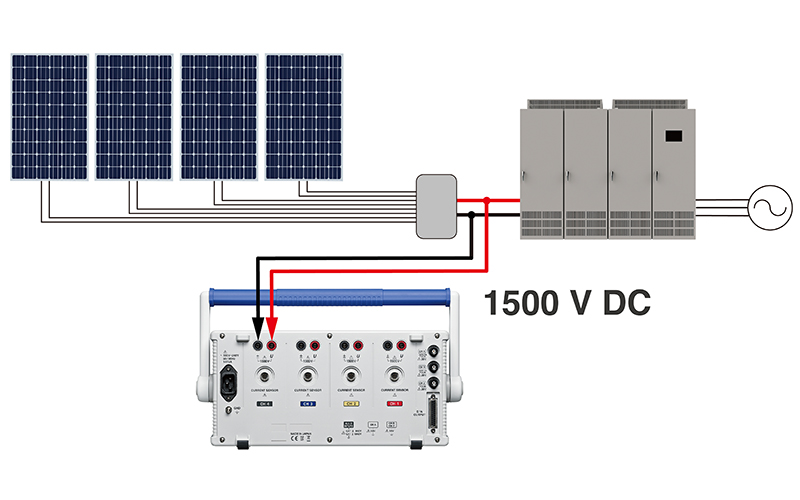
The PW3390’s measurement ranges provide coverage up to 1500 V. That lets the instrument measure 1500 V DC from high-voltage solar inverters (or PV inverters), satisfying Company A’s request.
With regard to current measurement, Hioki offers a large selection of current sensors developed in-house so that customers can choose the best devices for their applications. For grid frequencies of 50 Hz/60 Hz, our general-purpose sensors can measure a maximum of 6000 A. For DC, we offer clamp-type high-accuracy sensors that can measure up to 1000 A, as well as pass-through high-accuracy sensors that can measure up to 2000 A.
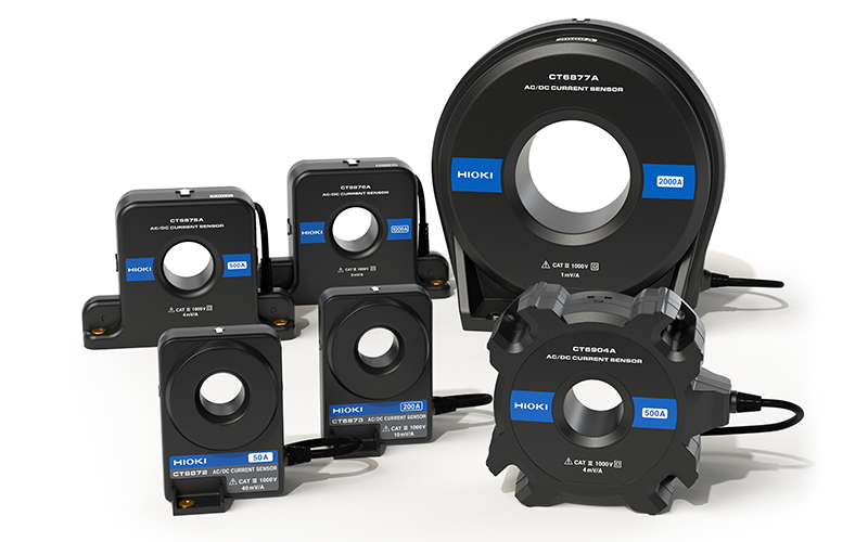 Pass-through type high accuracy sensor
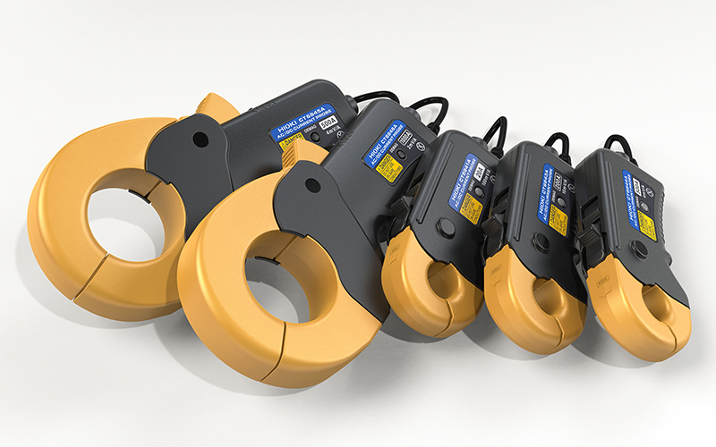 Clamp type high accuracy sensor
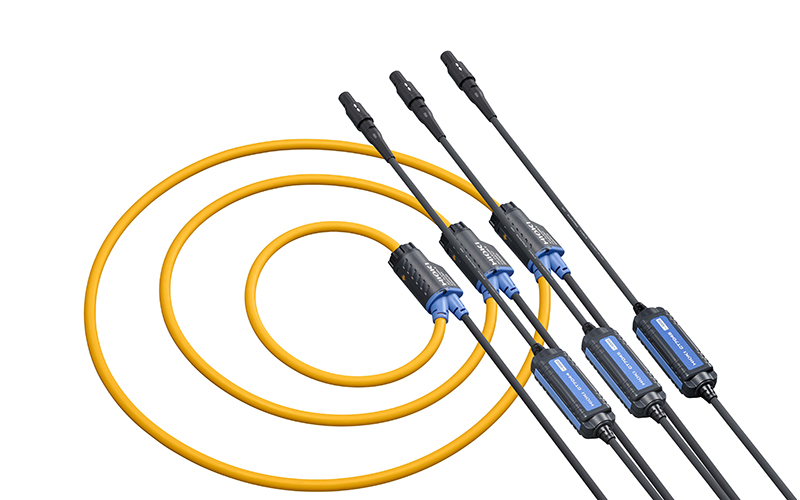 General purpose sensor on grid side
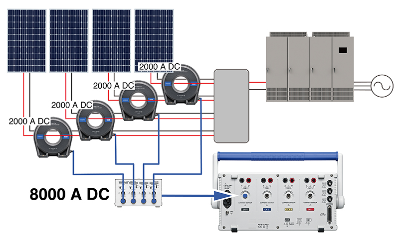
In addition, the dedicated Sensor Unit CT9557 can be used to add and output the waveforms of multiple current sensors. In this way, the PW3390 can accept current input of up to 8000 A on a 4-wire multi-cable circuit line, allowing it to measure power conversion efficiency at a high level of accuracy when large currents are involved, solving the issue described above.
Delivering high, R&D-level accuracy in a small, lightweight, and portable package
Despite being small and light enough to carry with one hand, the PW3390 provides high measurement accuracy on par with power analyzers used to evaluate performance at the R&D stage. The ability to use the same instrument in R&D and–due to its small size and low price–at manufacturing sites means there will be no disparity in measurements taken in R&D and manufacturing. Moreover, production lines can be set up more quickly since the same instrument used in R&D can be integrated into those lines. The PW3390 can be used in the field as well, so the same results can be obtained during maintenance inspections.

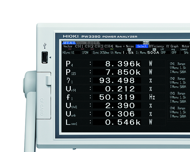 P4: DC power (panel output), P123: 3-phase power (Solar inverter output), η1: Conversion efficiency, Urf4: Ripple factor, F1: Frequency, Uthd1: Voltage total harmonic distortion, Uurb: Unbalance rate, Loss1: Loss
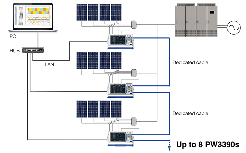
Acquiring synchronized data from up to 8 instruments with 4 channels each (32 channels)
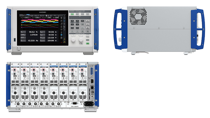
The PW3390 provides four input channels. By connecting eight PW3390s with a dedicated cable and using the instruments’ synchronization function, you can synchronize the instruments’ control signals and internal clocks. In this way, you can connect up to eight PW3390s and acquire synchronized data from 32 channels, which can then be centrally managed using a computer.
Support for even higher voltages and simultaneous measurement of multiple circuits
As power generation systems that use natural energy gain wider adoption, solar inverters (or PV inverters) are expected to handle voltages even higher than 1500 V, and even larger currents. In addition, multi-string solar inverters are being developed to maximize the amount of power generated by photovoltaic systems. Multi-string solar inverters controls the operating point to produce the maximum amount of power for each string. Due to the increased number of circuits, more points need to be measured in evaluation test.
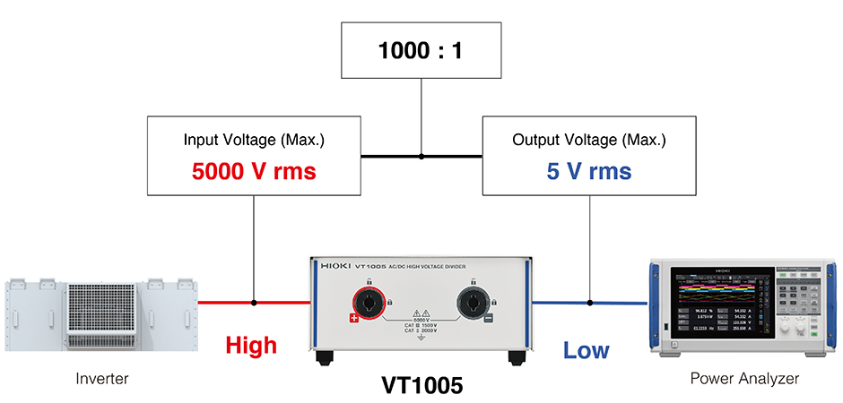
Hioki offers the optional AC/DC High Voltage Divider VT1005, which can be combined with a power analyzer to accomplish safe measurement (CAT II 2000 V or CAT III 1500 V) of high voltages of up to 5000 V. Also, the PW8001, the flagship model of the power analyzer (which is a high-end model of the PW3390), can analyze (display and record) the power of up to 8 channels.The VT1005 divides high voltages from devices such as solar inverters (or PV inverters) and inverters and outputs them to a power analyzer. Since the device provides coverage for a broad band of frequencies that extend from the fundamental wave to switching frequencies, it allows power analyzers to accurately capture all components of inverter output-side power: fundamental wave, switching frequencies, and harmonics. When used with the PW8001, Hioki’s flagship model, which can accommodate up to eight channels of input, the VT1005 allows efficiently improvements in inverters that use SiC power devices to be measured at the 0.1% level.
Hioki instruments can be used not only in R&D, but also in a wide range of measurement applications, including at manufacturing sites and in the field. We’re happy to provide demonstration instruments and samples so that prospective customers can conduct measurement tests. Please get in touch with any measurement issues you’d like to resolve or instruments in which you're interested.
Learn more
Technical Article