Calculate a Resolver’s Angle of Rotation
What is a Resolver?
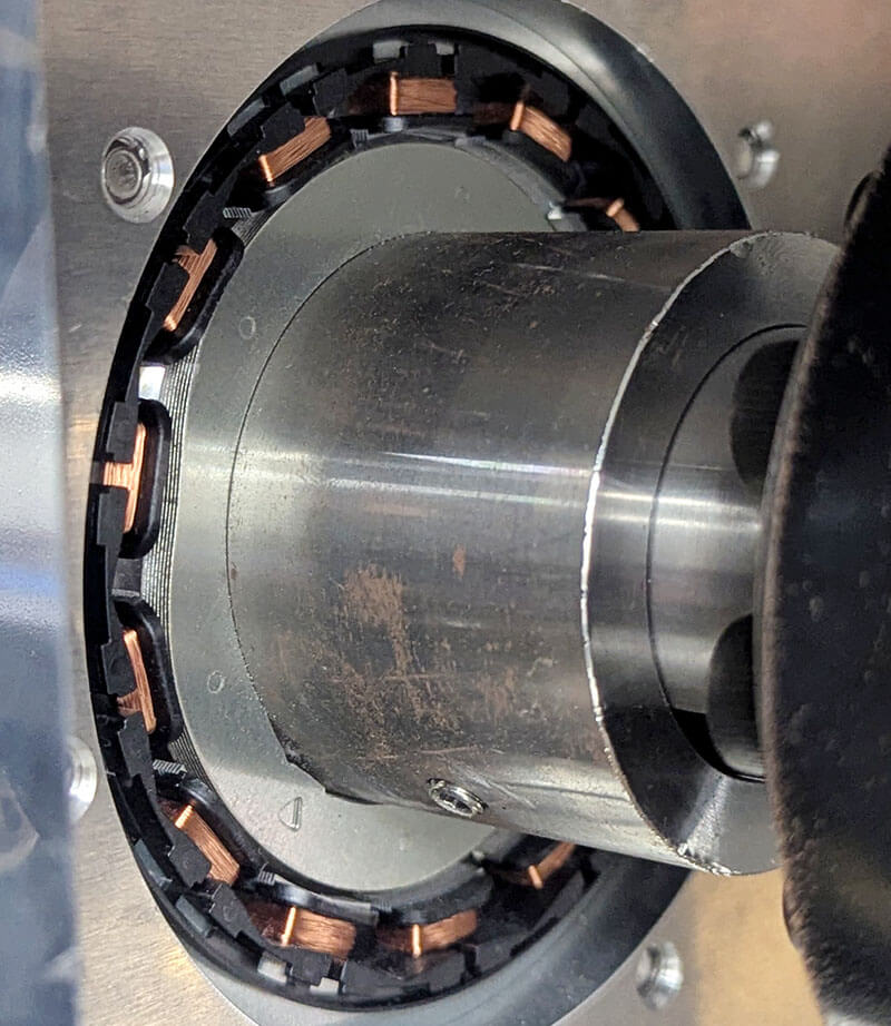
A resolver is a rotary transformer consisting of a sensor that is used to accurately measure a rotor's angular position relative to the stator, as well as speed of rotation. It has no electronic parts, which makes it suitable for long-term use in harsh and demanding environments including those with high temperatures, vibrations, radiation and residue, for example heavy industrial motors, servo motors, and automobiles. The digital version of a resolver is a rotary encoder.
How are Resolvers Used?
A resolver is used as a feedback device to ensure that a rotor will rotate properly, and by extension, the motor will accelerate, slow down, or stop at precise moments. Manufacturers using robotic equipment depend on reliable servo motors to control arm movement while it operates at optimal speeds, making both safety and efficiency high priorities.
Resolvers are also a critical part of a motor on hybrid or electric vehicles to serve as the rotor position sensor. In order for the car’s AC synchronous motor setup to function properly, the computer needs to know the position of the rotor at any given time so that the appropriate stator winding is charged with the proper phase current from the inverter - a resolver is essentially a sensor that helps to do that.
The Memory HiCorder as a Resolver Digital Converter
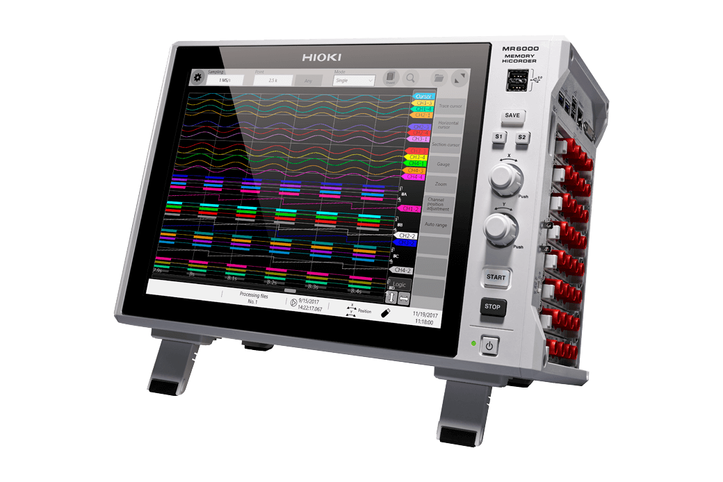
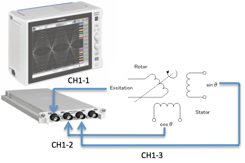
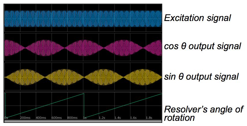
During motor development, a multi-channel Memory HiCorder MR6000 can be used as a resolver digital converter to evaluate the rotor position and the rotational speed based on the signal waveforms. The ability to capture the resolver’s excitation signal (reference voltage signal) and two output signals (sine and cosine voltage) with a single analog unit, and then using another channel to make calculations for the rotation angle, makes it a turnkey solution for this application. The Memory HiCorder’s high 16-bit resolution enables customers to capture the slight changes in the output waveforms that serves as valuable information for advancing the precision of the resolver’s position sensing during development.
How to Set Up and Measure
• Input the resolver’s excitation signal and output signal to the 4ch Analog Unit U8978 (range: 100mVf.s. to 40Vf.s.)
• The remaining input slots of the MR6000 can be fitted with other modules to let you measure temperature, control signals, torque, and current signals at the same time in order to evaluate the effect of other factors on the signal as well as measure additional physical properties of a motor, especially EV motors that require highly efficient but precise control.
• Use the built-in waveform calculation function to calculate the resolver’s angle of rotation and display on the screen
-
Calculate angle of motor rotation from input/output signals transmitted via the resolver [2101.86KB]