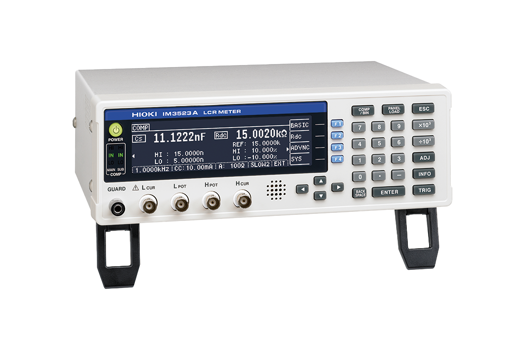
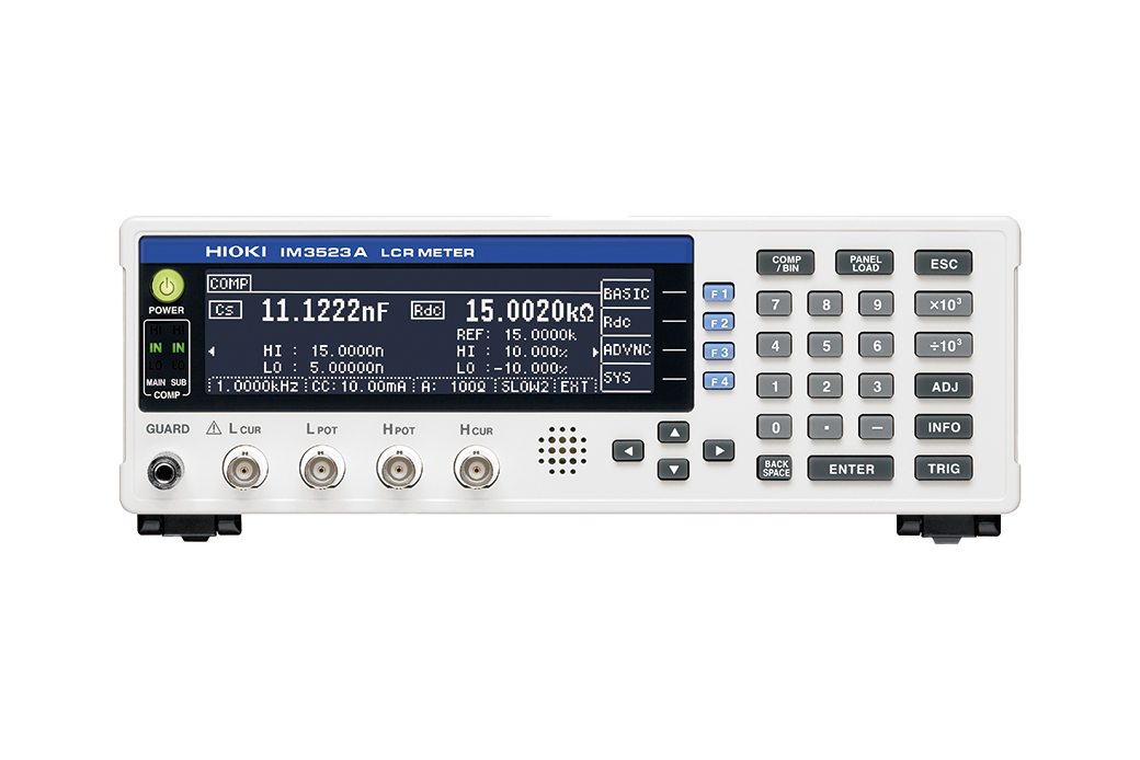
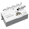
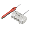
LCR METER IM3523A
Ideal for Production Lines of Electronic Parts and Automated Testing
Hioki LCR Meters and Impedance Analyzers range from 1 mHz to 3 GHz devices to suit a wide range of applications in the testing of electronic components. The IM3523A is designed for basic measurement on production lines so that it can be offered at a low price point, and delivers improved measurement reliability thanks to its contact check function.
Key Features
- ±0.05% accuracy with wide measurement range (DC, 40Hz to 200kHz, 5mV to 5V, 10uA to 50mA)
- Rapid 2 msec test time
- Built-in comparator and BIN functions
- Non-stop testing over mixed measurement conditions such as C-D(120 Hz) and ESR(100 kHz) at 10 times the speed of previous models (compared with Model 3532-50)
Model No. (Order Code)
| IM3523A |
|---|
Application information
Download the sample application and view the Communications Command User Manual.

Accuracy calculation information
Calculate accuracy by simply entering a numerical value.

Basic specifications
| Measurement modes | LCR (Measurement with single condition), Continuous testing (Continuous measurement under saved conditions) | |||||
|---|---|---|---|---|---|---|
| Measurement parameters | Z, Y, θ, X, G, B, Q, Rdc (DC resistance), Rs (ESR), Rp, Ls, Lp, Cs, Cp, D (tanδ) | |||||
| Measurement range | 100 mΩ to 100 MΩ, 10 ranges (All parameters defined in terms of Z.) | |||||
| Displayable range | Z, Y, Rs, Rp, Rdc, X, G, B, Ls, Lp, Cs, Cp : ± (0.00000 [unit] to 9.99999G [unit]) Real value display for Z and Y only θ: ± (0.000° to 180.000°), D: ± (0.00000 to 9.99999) Q: ± (0.00 to 99999.9), Δ%: ± (0.0000% to 999.999%) |
|||||
| Basic accuracy | Z : ±0.05% rdg. θ: ±0.03° | |||||
| Measurement frequency | 40 Hz to 200 kHz (5 digits setting resolution) | |||||
| Measurement signal level | V mode, CV mode: 5 mV to 5 Vrms, 1 mVrms steps CC mode: 10 μA to 50 mArms, 10 μArms steps |
|||||
| Output impedance | 100 Ω | |||||
| Display | Monochrome LCD | |||||
| Measurement time | 2 ms (1 kHz, FAST, representative value) | |||||
| Functions | Comparator, BIN measurement (classify function), Panel loading/saving, Memory function | |||||
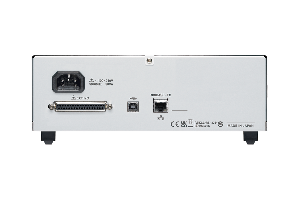
| Interfaces | EXT I/O (handler), USB communication (full-speed), LAN | |||||
| Power supply | 100 to 240 V AC, 50/60 Hz, 50 VA max | |||||
| Dimensions and mass | 260 mm (10.24 in) W × 88 mm (3.46 in) H × 203 mm (7.99 in) D, 2.1 kg (84.7 oz) | |||||
| Included accessories | Power cord × 1 , CD-R (Includes Instruction manual, PC commands and Sample software) × 1, Startup guide× 1, Operating precautions× 1 | |||||
Probe and Test fixtures (15)
When using the 9268-10 or 9269-10, external constant-voltage and constant-current sources are required.
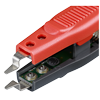
To replace the tip on the L2001, regular size, bundled with the L2001
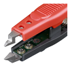
To replace the tip on the L2001, small size
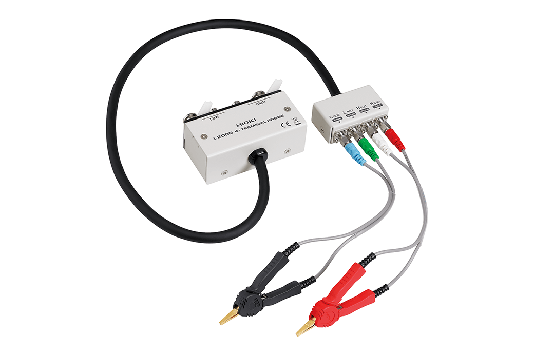
Cable length 1 m (3.28 ft), DC to 8 MHz(Can be measured up to 10 MHz, when combined with the special order model IM3536-01), impedance characteristics of 50 Ω, 4-terminal pair configuration, measurable conductor diameter: ø0.3 (0.01 in) to 5 mm (0.20 in)
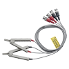
Cable length 1 m (3.28 ft), DC to 200 kHz, impedance characteristics of 50 Ω, 4-terminal pair configuration, measurable conductor diameter: ø0.3 (0.01 in) to 5 mm (0.20 in)
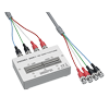
Cable length 1 m (3.28 ft), DC to 8 MHz, impedance characteristics of 50 Ω, 4-terminal pair configuration, measurable conductor diameter: ø0.3 (0.01 in) to 1.5 mm (0.06 in)
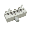
Direct connection type, DC to 8 MHz(Can be measured up to 10 MHz, when combined with the special order model IM3536-01), measurable conductor diameter: ø0.3 (0.01 in) to 2 mm (0.08 in)
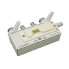
Direct connection type, DC to 8 MHz(Can be measured up to 10 MHz, when combined with the special order model IM3536-01), Test sample dimensions:1 mm (0.04 in) to 10 mm (0.39 in)
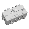
Direct connection type, 40 Hz to 8 MHz, maximum applied voltage of DC ±40 V
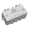
Direct connection type, 40 Hz to 2 MHz, maximum applied current of DC 2 A
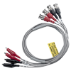
Cable length 1 m (3.28 ft), DC to 200 kHz, impedance characteristics of 50 Ω, measurable conductor diameter: φ0.3 mm (0.01 in) to 2 mm (0.08 in)
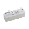
Direct connection type, For measuring SMDs with electrodes on the side; DC to 120 MHz, test sample dimensions: 3.5 mm ±0.5 mm (0.14 in ±0.02 in)
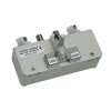
Direct connection type, For measuring SMDs with electrodes on the bottom; DC to 120 MHz, test sample dimensions: 1.0 mm (0.04 in) to 4.0 mm (0.16 in) wide, max. 1.5 mm (0.06 in) high

