Weld Quality Inspection by Resistance Measurement
Introduction
Batteries, motors, and inverters are indispensable key components in today's increasingly electrified automobiles. Since these devices draw large currents during operation, even the slightest faulty connection can generate heat, and their performance and safety depend greatly on the quality of the connection.
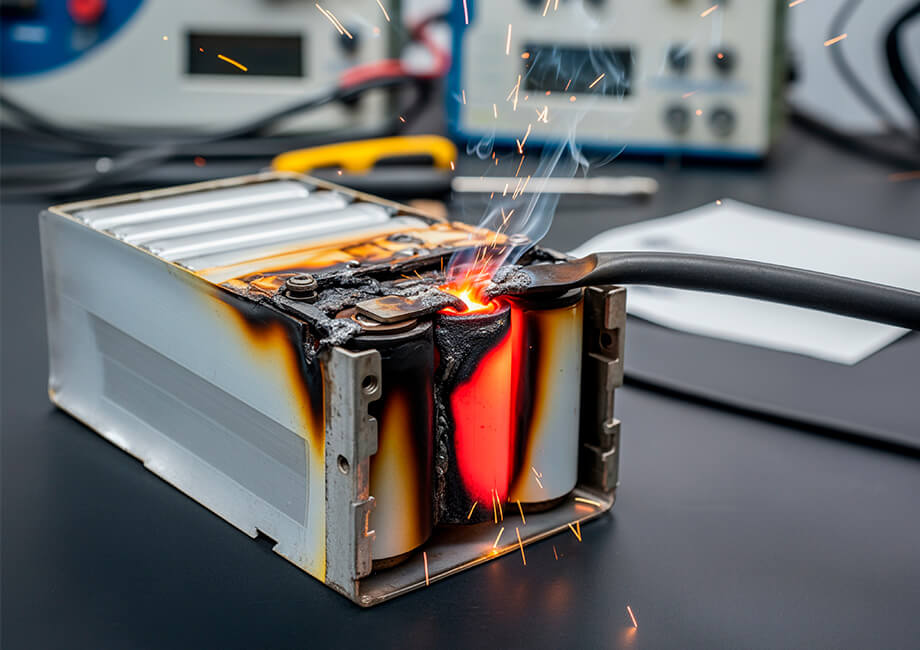
In particular, battery heat generation is a major issue, and in PHEVs and BEVs, abnormal heat generation can occur due to weld defects caused by the high current during ultra-rapid charging. Since abnormal heat generation can shorten battery life and, in the worst case, lead to a fire accident, inspection of weld quality during the manufacturing process is extremely important.
This problem is also true for large energy storage systems (ESSs), which are in increasing demand as renewable energy sources become more prevalent; ESSs must be highly durable to withstand long-term use, and the quality of the weld directly affects the efficiency and safety of the system.
Temperature Effects on Weld Resistance Measurement
When measuring weld resistance, the temperature of the measurement target is high immediately after welding.
As temperature rises, the resistance of metals also increases. This occurs because the thermal vibration of metal atoms caused by the high temperature impedes the movement of free electrons. Due to this temperature dependence of resistance, measurements taken under different temperature conditions—such as immediately after welding—cannot yield accurate results.
Conventional resistance meters such as the RM3545 have a TC (Temperature Correction) function that converts the measured resistance at the sample’s temperature to its equivalent value at a reference temperature.
This method has two limitations making it unsuitable for high-temperature samples such as immediately after welding.
- External temperature sensors cannot track the rapid post-welding cooling fast enough.
- Cooling generates changing thermal electromotive force (thermal EMF), which is too fast for the OVC function to track.
To solve these issues, the RM3546 introduces the A-TC (Advanced Temperature Correction) method for precise post-welding measurements.
A-TC function
A-TC eliminates external temperature sensors by measuring the resistance of an unwelded section of the sample1. It uses Advanced Offset Voltage Compensation (A-OVC) to dynamically track and correct changing thermal EMF. This 4-terminal, 8-wire technique (two 4-terminal pairs: weld + temperature sections) enables instantaneous conversion to reference-temperature resistance values, regardless of the target's temperature state.
- 1:Using the same measurement principle as the ΔT function of the RM series resistance meters.
Example of a typical measurement setup
The A-TC function implemented in the RM3546 requires the user to measure resistance of an unwelded section of the DUT (see Fig. 1). Therefore, the user ends up measuring two locations on the DUT (unwelded area for A-TC and welded area for weld resistance). Since both resistance measurements require high-precision, each uses a 4-terminal connection. This necessitates the use of the Z3003 multiplexer (see Fig. 2).
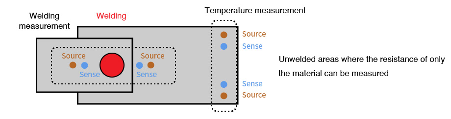
Fig. 1. Example of 8 measurement points.
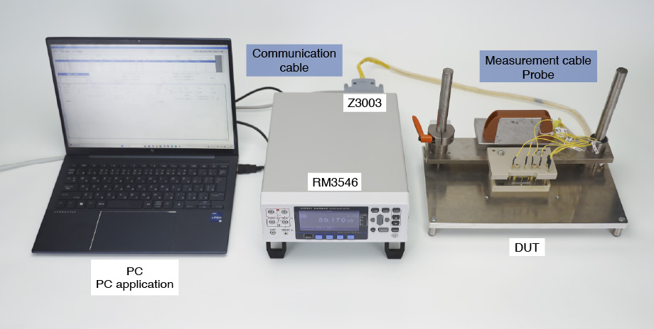
Fig. 2. Example of equipment configuration for weld resistance measurement.
In many cases where resistance measurements are made on metal welds, the measured values are in the order of μΩ.
In such ultra-low resistance measurements, accuracy is greatly affected by temperature variations as well as probe misalignment. These error sources necessitate the creation of application-specific fixtures that match the shape of the measurement target.
For more details on such test fixtures and probing techniques, please see Mastering Probing for Accurate Low Resistance Measurements.
Measurement procedure
For detailed procedures, refer to the instruction manual.
- 1.Measure the reference resistance of the temperature measurement section
- 2.Determine2 the temperature coefficient of the temperature measurement section
- 3.Measure3 the temperature coefficient of the welding measurement area with a good sample
- 4.Take A-TC measurements3 immediately after welding on production lines
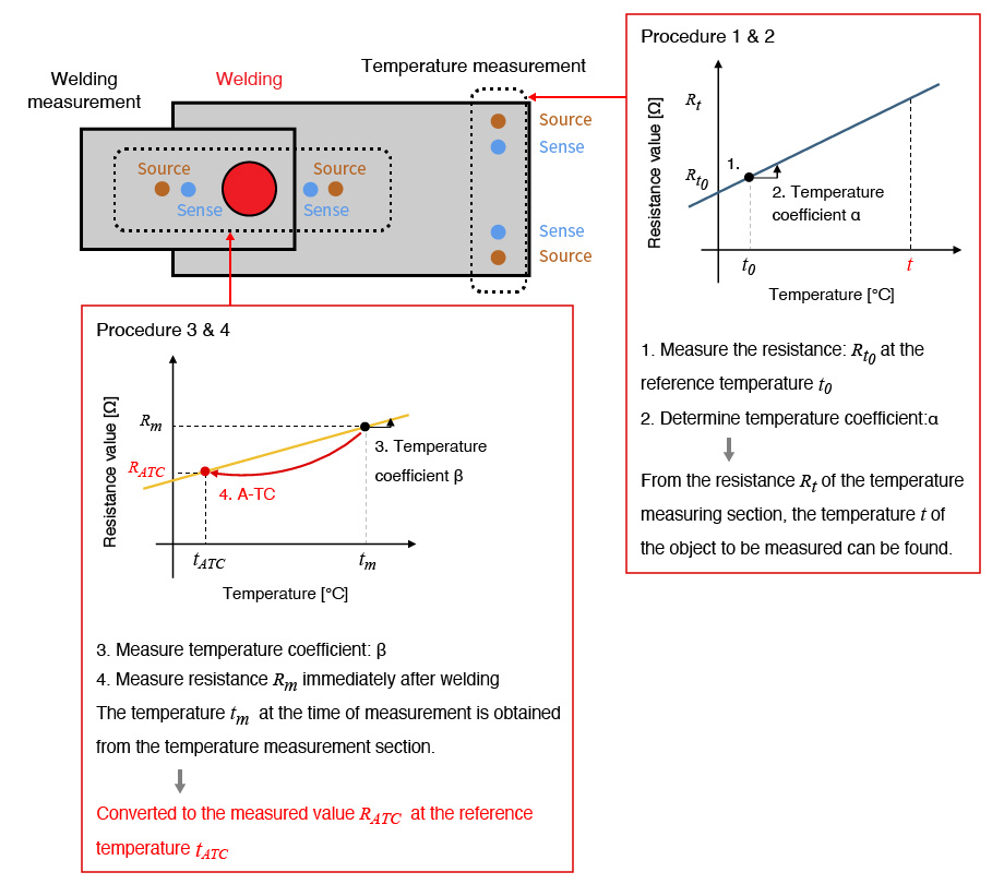
Fig. 3. A-TC correction flow
- 2:For temperature coefficient, test using a thermostatic chamber and thermistor, or use published reference values for the temperature coefficient (deprecated for alloys due to large errors).
- 3:The RM3546’s PC application can be used for measurement.
Measurement Examples
The following are measurement results for a welding sample similar to the one in Fig. 4.
- Measurement object: spot welding sample (welding current: 10 kA)
- Measuring method: a heat gun was used to heat the object to 215°C, and the process of cooling was measured using the A-TC function with a reference temperature of 22°C.
- The dimensions of the test coupon and the location of the probe points are shown in Fig. 4.
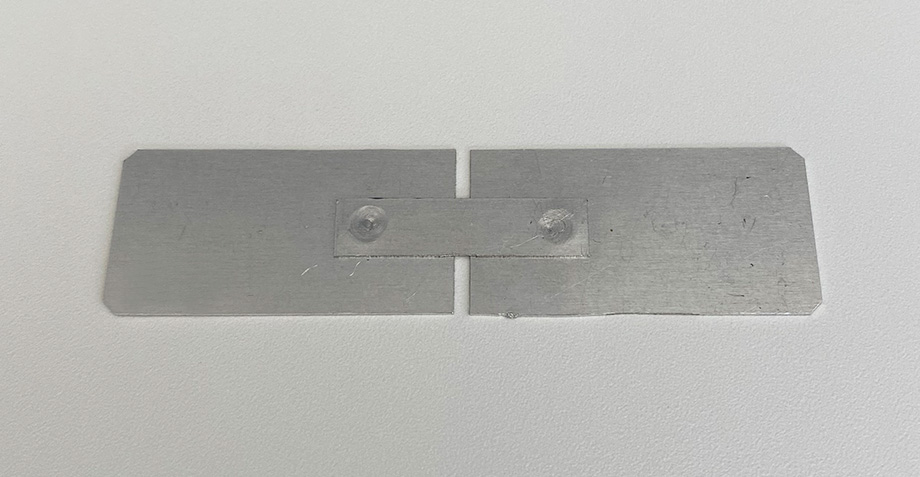
Fig. 4. Spot Welding Sample
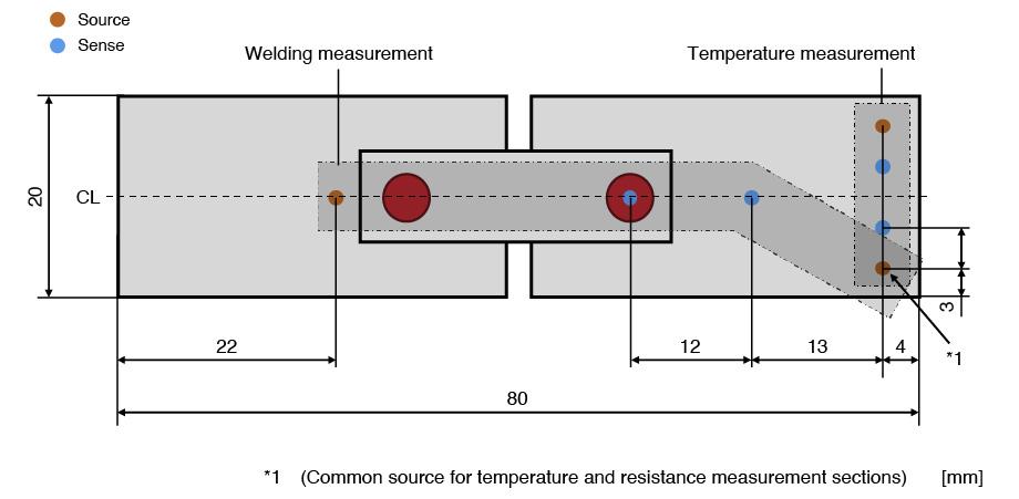
Fig. 5. Probing dimensions
Measurement results
Measured values were obtained using the A-TC function during the cooling process from 215°C to 33°C (see Fig. 6). The measured values were within the range of 85.7 μΩ and 86.2 μΩ after A-TC correction with the reference temperature of 22°C.
The measured resistance value at 22°C was 86.1 μΩ, making the measured values within 0.5% of the true value.
In this experiment, it took more than 15 minutes for the sample to cool down from 215°C to room temperature of 22°C. Regardless, by using the A-TC function to correct the temperature, we were able to obtain very accurate measurements at high temperatures in the midst of significant temperature change.
The A-TC function improves welding throughput by eliminating the time it takes to wait for a sample to reach steady-state temperature.
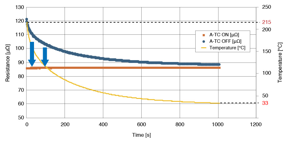
Fig. 6. Resistance measurement with A-TC on/off and temperature measurement.
Summary
Welding resistance measurement using a resistance meter is a reliable method of welding inspection. It is a very sensitive measurement with resolution as fine as μΩ.
The A-TC method is fast, non-destructive, and provides quantitative data of welding quality.
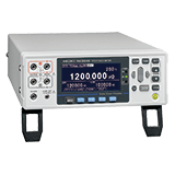
The Hioki's RM3546 resistance meter enables highly accurate resistance measurement with 1 nΩ resolution and advanced temperature compensation function (A-TC function).
Watch the demonstration video here to see the A-TC function in action.
The RM3546 application can be downloaded from here.
For a demonstration or consultation on a specific application, please contact us.