Lithium-ion Battery Weld Quality Testing
What is weld quality testing of lithium-ion batteries?
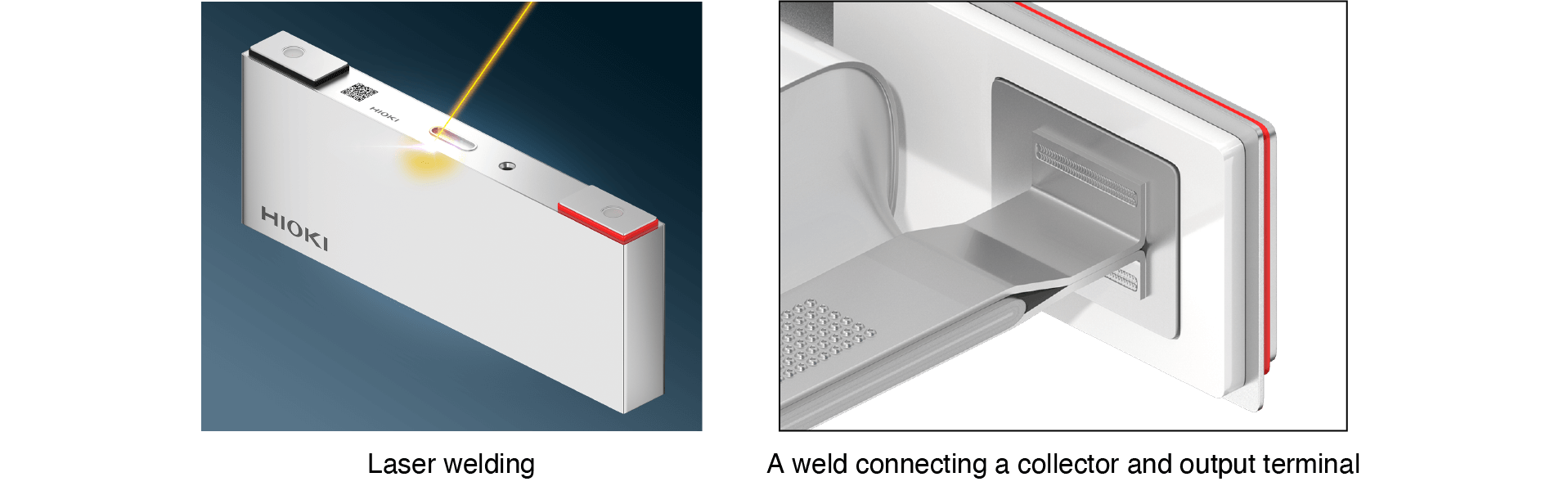
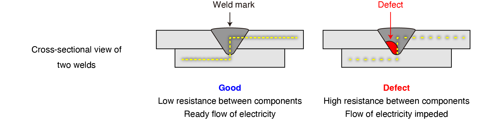
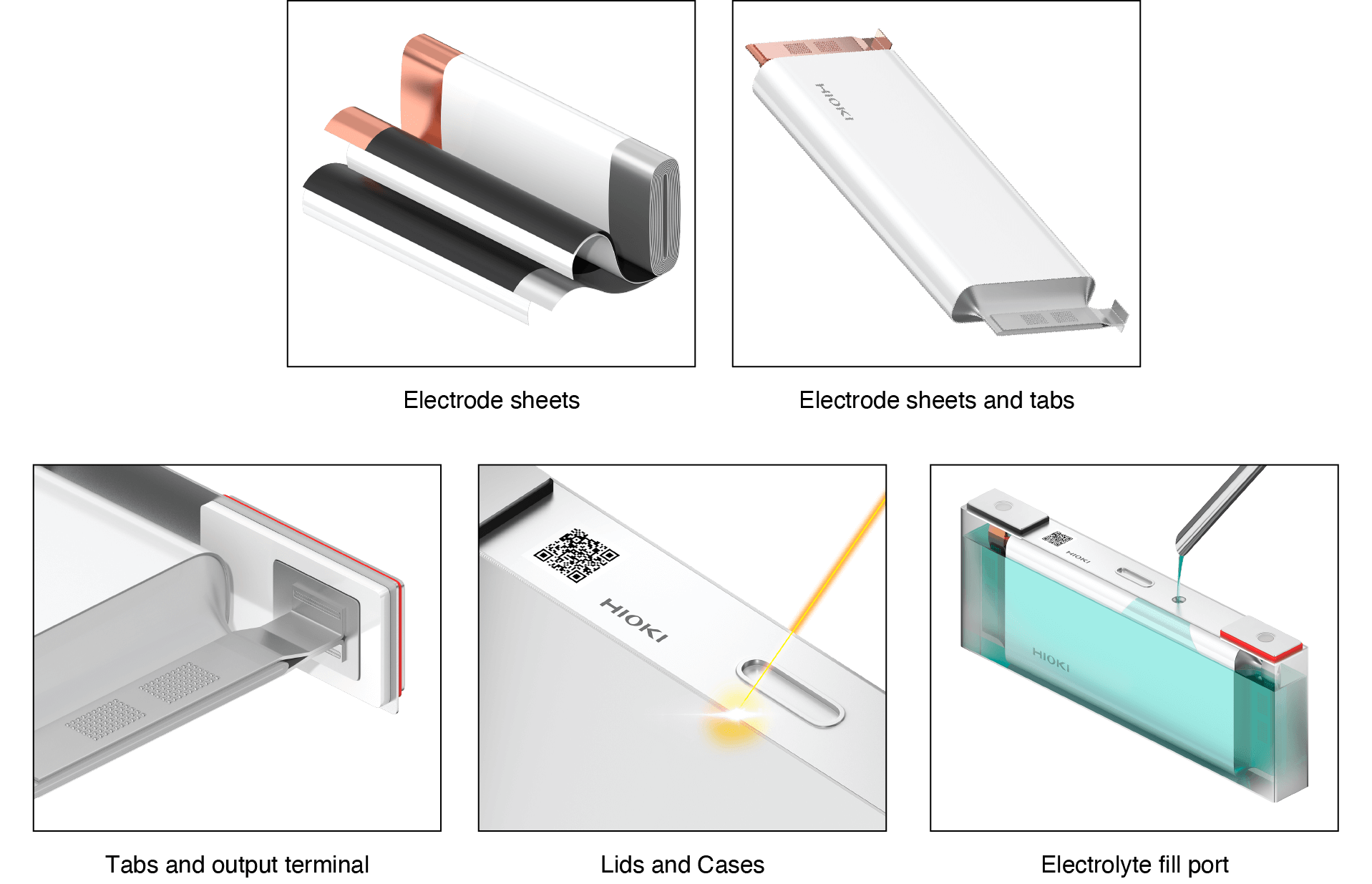
Several components of lithium-ion batteries - electrode metal foils (current collectors), tabs and output terminals - are welded together using technologies such as laser or ultrasonic welding. If these welds are inadequate, the electrical resistance between components will increase. In weld quality testing, resistance values between components are measured to ensure weld quality.
When to test weld quality
Weld quality testing is carried out in every process that involves welding, including welding of electrode sheet tabs as well as welding between collectors and output terminals.
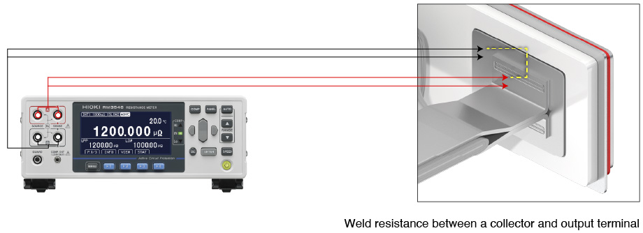
How to measure weld resistance
Weld resistance is measured using a DC resistance meter that’s specifically designed for low-resistance measurement. DC resistance meters apply a constant DC current to the testing point. The meter then detects a minuscule voltage generated by the applied current and calculates the resistance value.
Resistance meters are available in DC and AC variants. DC resistance meters can measure low resistance values more accurately than AC resistance meters. (AC resistance meters are used to measure batteries’ internal resistance.)
(Learn more: Differences of Resistance Measurement Methods)
Key considerations when choosing an DC resistance meter
When testing the weld resistance between components, it’s important to use an instrument that can accurately measure low resistance values. The following considerations should be taken into account when choosing an DC resistance meter:
- 4-terminal method (Four-terminal measurement)
- Measurement range and resolution
- Noise resistance
4-terminal method (Four-terminal measurement)
When measuring low resistance levels of 1 Ω or less, internal resistance is measured using the 4-terminal method. Resistance can be measured using either the 4-terminal method or the 2-terminal method. Since measured values obtained using the 2-terminal method include path resistance (i.e. wiring resistance and contact resistance), low resistance cannot be measured accurately.
(Learn more: 4-terminal resistance measurement method)
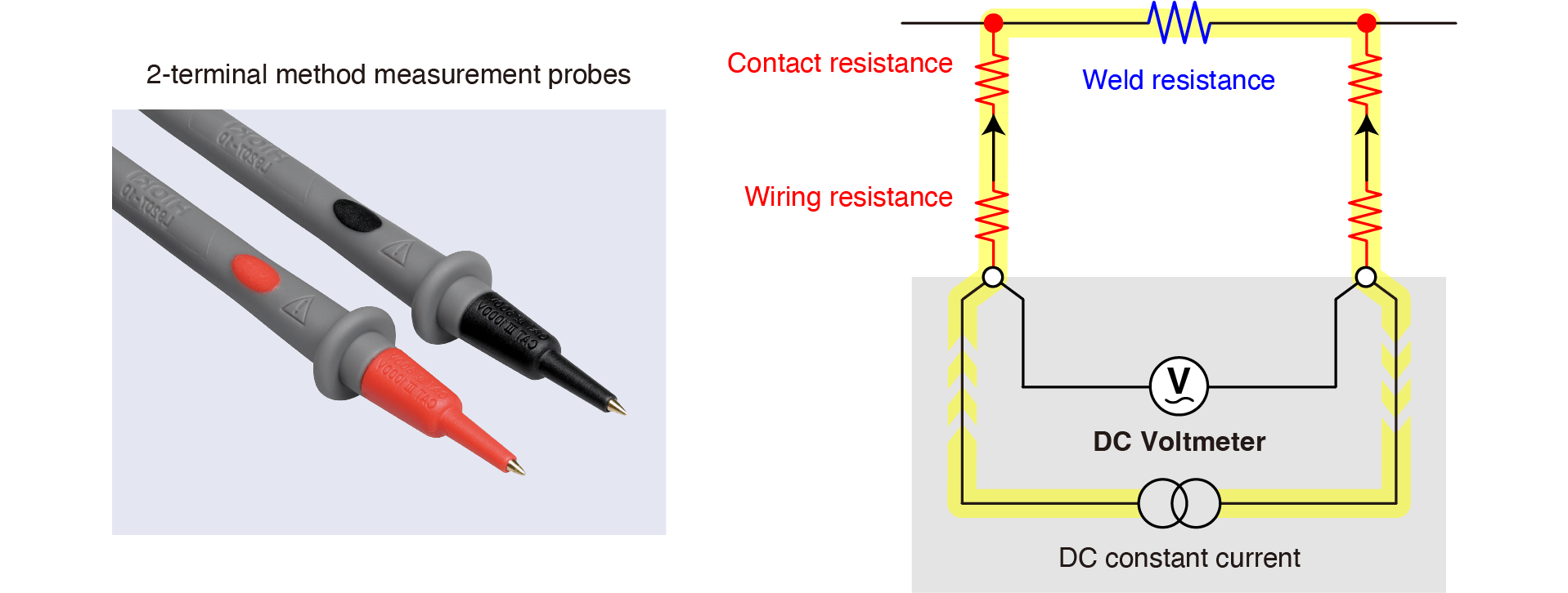
Detected voltage = Applied current × (Weld resistance + Contact resistance + Wiring resistance)
The resistance value is calculated from the detected voltage. The value can include excess resistance components.
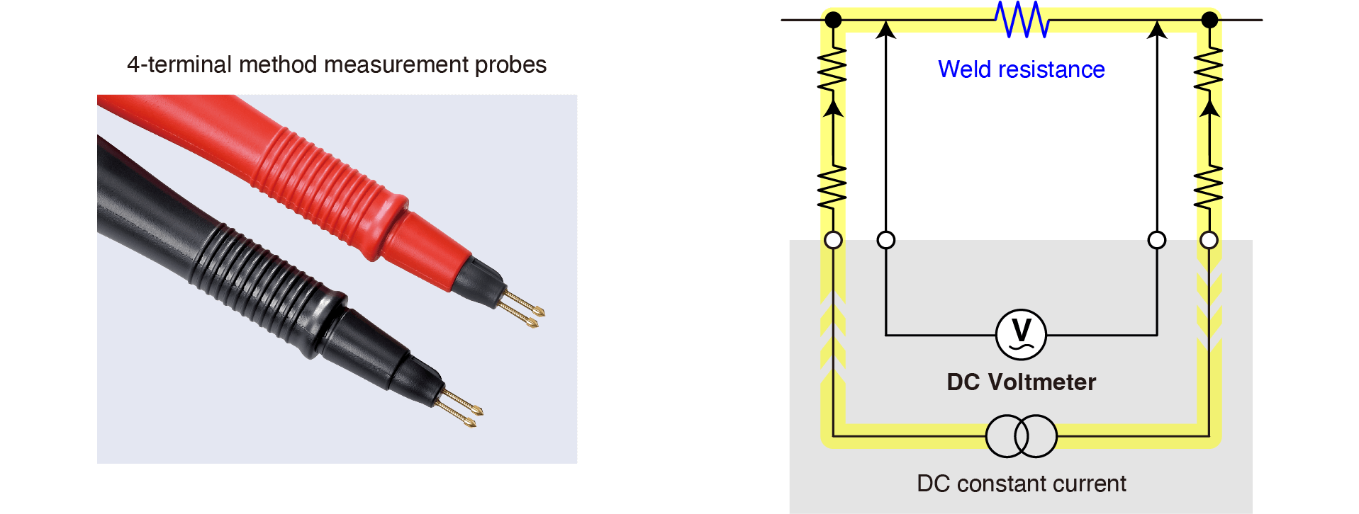
Detected voltage = Applied current × Weld resistance
The resistance value is calculated from the detected voltage. It does not include any excess resistance components.
Measurement range and resolution
To measure low resistance levels of 1 Ω or less, an instrument needs to provide a milliohm-order measurement range as well as microohm-order resolution. Low resistance levels on the order of milliohms can not be measured accurately if the range and resolution is not enough.
Noise resistance
Even if an instrument’ s specifications provide a good measurement range, resolution, and measurement accuracy, it may not be possible to accurately measure resistance values. In some cases, the surrounding electric noise may make measured values unstable and prevent the instrument from presenting precise readings. (There are various sources of noise, including power supplies or production equipment.)
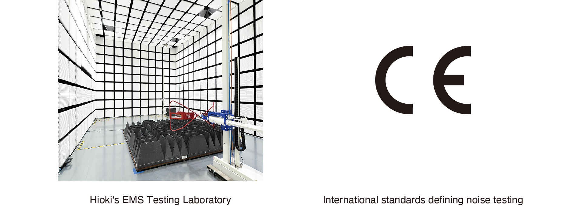
During the development of measuring instruments, noise resistance tests are generally performed to verify their performance in noisy environments. Products not subjected to such testing may not fulfill their measurement specifications when used on production lines.
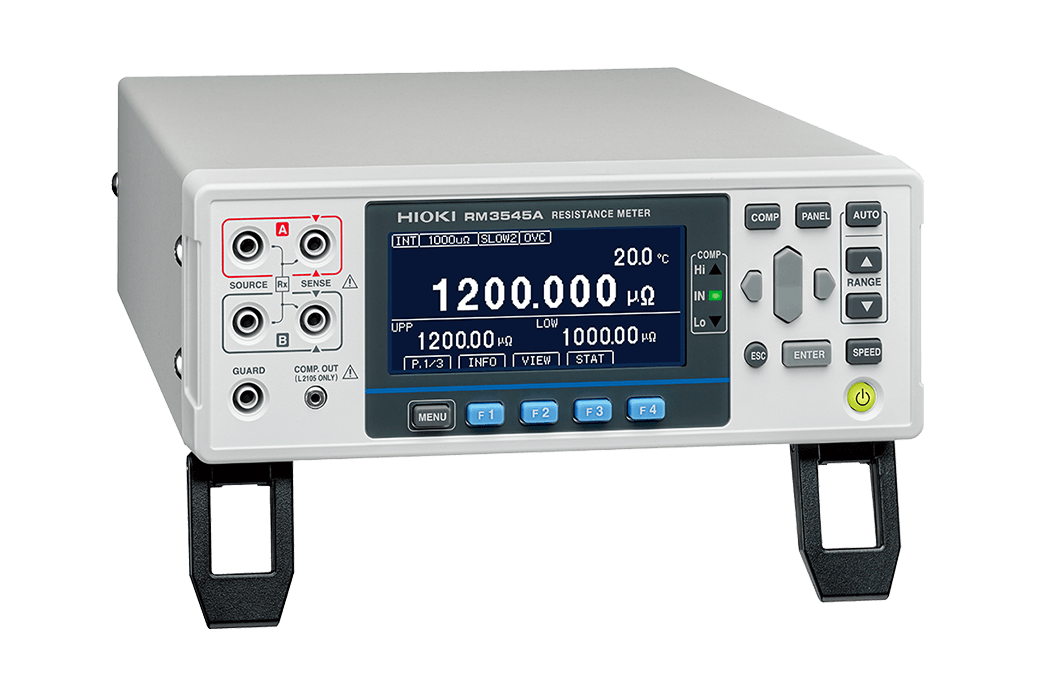
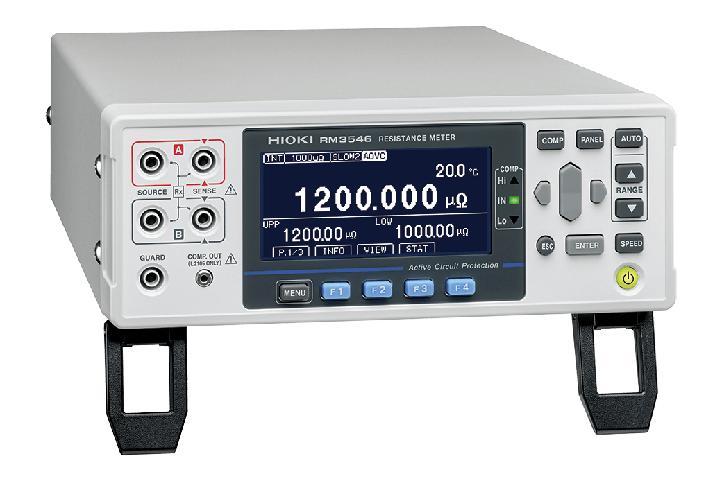
DC resistance meters from Hioki
Hioki’ s DC resistance meters are working at battery manufacturers around the world. The following models are used in weld quality testing in battery cell production processes.
Available: ✔, Not available: −
| Specifications, functions | RM3545 | RM3545-01 | RM3545-02 | RM3545A-1 | RM3545A-2 | RM3546 |
|---|---|---|---|---|---|---|
| Maximum allowable voltage | - | ±60 V DC, or 30 V AC rms and 42.4 V AC peak | ||||
| Minimum measurement range | 10 mΩ | 1000 μΩ | ||||
| Maximum resolution | 10 nΩ | 1 nΩ | ||||
| Measurement range | 0.000 00 mΩ (10 mΩ range) to 1200.0 MΩ (1000 MΩ range), 12 ranges | 0.000 μΩ (1000 μΩ range) to 1200.0 MΩ (1000 MΩ range), 13 ranges | ||||
| Measurement current | 1 A | |||||
| - | 500 mA | |||||
| 100 mA, 10 mA, 1 mA, 500 μA, 100 μA, 50 μA, 10 μA, 5 μA, 1 μA, 1 μA 以下, 100 nA | ||||||
| Offset voltage compensation | OVC | OVC or A-OVC | ||||
| Temperature correction | TC | TC or A-TC | ||||
| Maximum allowable route resistance (reference value) 1 A range | 1.5 Ω | 3.5 Ω(PR:On) 2.6 Ω(PR:Off) | ||||
| Maximum allowable route resistance (reference value) 500 mA range | - | 9 Ω(PR:On) 6.1 Ω(PR:Off) | ||||
| Pure resistance mode (PR) | - | 1000 μΩ, 10 mΩ, 100 mΩ ranges | ||||
| Low-power mode (LP) | 1000 mΩ, 10 Ω, 100 Ω, 1000 Ω ranges | - | ||||
| USB | ✔ | ✔ | ✔ | ✔ | ✔ | ✔ |
| RS-232C | ✔ | ✔ | ✔ | ✔ | ✔ | ✔ |
| LAN | - | - | - | ✔ | ✔ | ✔ |
| GP-IB | - | ✔ | - | - | - | - |
| EXT. I/O | ✔ | ✔ | ✔ | ✔ | ✔ | ✔ |
| Multiplexer | - | - | Max. 2*1 | - | Max. 2*1 | Max. 2*1 |
| Fuse | F1.6AH/250 V (replaceable) | Protected by internal circuitry (not replaceable) | ||||
| Dimensions | Approx. 215W × 80H × 306.5D mm (8.46W × 3.15H × 12.07D in.) | |||||
| Weight | Approx. 2.5 kg (5.5 lb.) | Approx. 3.2 kg (7.1 lb.) | Approx. 2.7 kg (6.0 lb.) | Approx. 3.4 kg (7.5 lb.) | ||
- *:2-wire: Max. 21 channels/unit, 4-wire: Max. 10 channels/unit