Measurement Error Factors in Reactor Loss Measurement and Key Considerations for High-Accuracy Measurement
What Is a Reactor?
A reactor is a component that uses an induction coil. It is used for suppressing inrush currents and high-frequency noise, as well as for smoothing current. There are two main types—DC reactors and AC reactors—and they are commonly found in power factor correction (PFC*1) circuits, buck/boost chopper circuits, and filter circuits.
In the electronic components field, these are often called "inductors," while in the power systems and power electronics fields—such as inverter applications—they are referred to as "reactors."
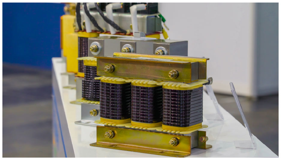 Fig. 1. Typical reactors (or inductors), commonly found in PFCs.
*1: PFC stands for Power Factor Correction. A PFC circuit is built into power supplies, inverters, and similar devices to shape the input current waveform and improve the power factor.
Typical Circuits Using Reactors
Boost Chopper Circuit in DC/DC Converters
Boost chopper circuits have traditionally been used to increase motor output in HEVs. In recent years, however, their adoption has been growing in EVs and FCVs (fuel cell vehicles). They are also used to boost panel voltage in solar power generation systems.
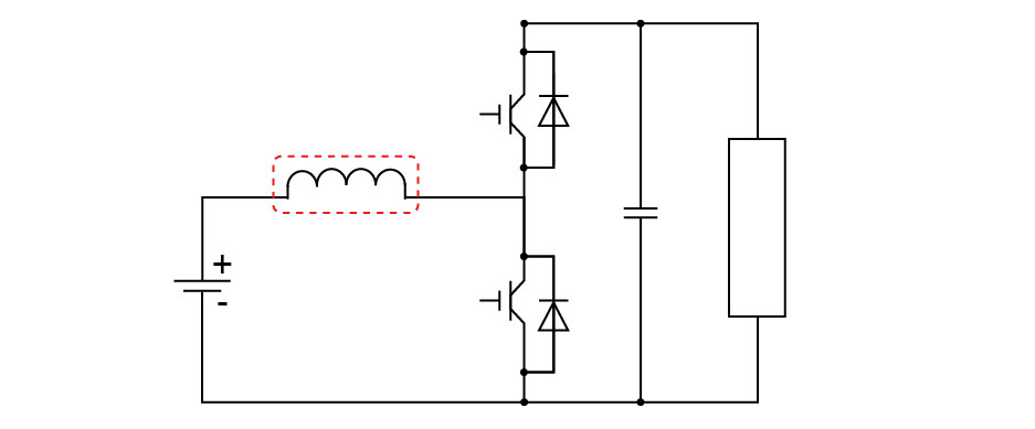 Fig. 2. Schematic of a boost chopper circuit used in DC/DC converters.
Interleaved PFC in AC/DC Converters
Interleaved PFC circuits are found in AC/DC converters for data centers, PFC circuits in air conditioners, and EV charging circuits.
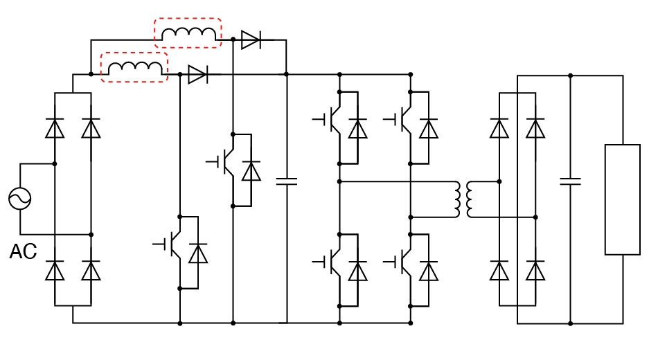 Fig. 3. Schematic of an interleaved PFC circuit used in AC/DC converters.
In both types of circuits, IGBTs have been the primary switching devices, with switching frequencies typically around 20 kHz. In recent years, however, SiC and GaN devices have been increasingly adopted, enabling higher breakdown voltages and faster switching speeds.
As these examples illustrate, reactors are an extremely familiar and essential component in the field of power electronics.
Why Reactor Loss Measurement Matters
In today's market—particularly in power electronics—there is a growing demand for smaller, lighter, and lower-loss power supplies in order to make the most efficient use of electrical energy.
Among the components used, passive components such as reactors account for a significant portion of a power supply's total volume and weight. As overall system efficiency—including inverters—continues to improve, the magnitude of reactor losses can no longer be ignored. Therefore, accurately measuring and understanding reactor losses is indispensable for design optimization, efficiency improvement, and achieving higher-performing power supplies.
Challenges in Reactor Loss Measurement
Measurement Using an LCR Meter
In the electronic components field, inductors are typically measured using an LCR meter. However, reactors exhibit level dependency; as the input signal increases, the magnetic flux density rises, causing the loss characteristics to change. As a result, small-signal measurements cannot reproduce the actual losses and behavior under real operating conditions.
Furthermore, LCR meters are limited to small-signal sinusoidal measurements, which places constraints on the signal levels that can be superimposed. If an attempt were made to measure under actual operating conditions, the excessive input could damage the measuring instrument.
Measurement Using a Power Analyzer
A power analyzer enables accurate loss measurement under actual operating conditions. However, when measuring reactor losses, the phase difference between voltage and current (power phase angle) is close to 90°, resulting in an extremely low power factor. For this reason, the most critical specification when selecting a power analyzer and current sensor is their phase accuracy across the high-frequency range, including the switching frequency.
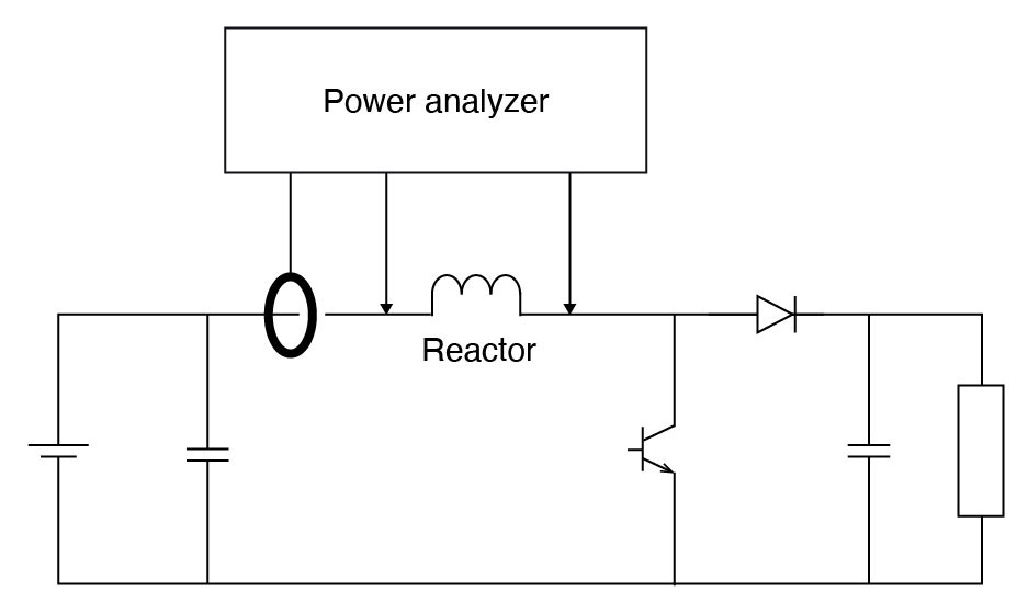
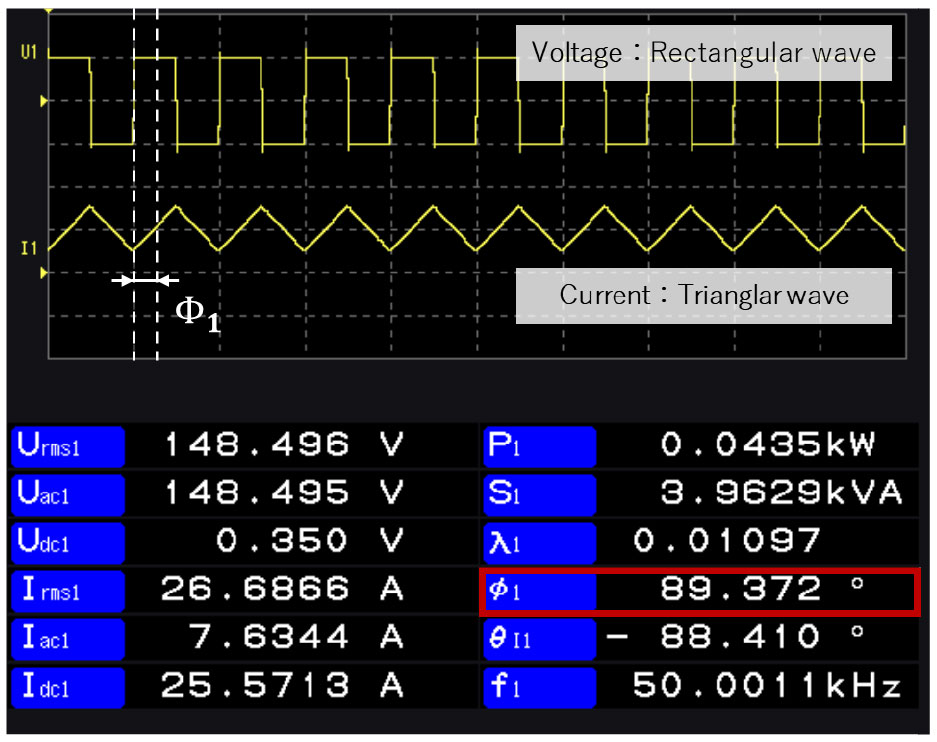
Fig. 4. Reactor waveform and measured values in a boost chopper circuit.
Proposed Solution
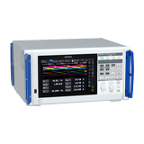
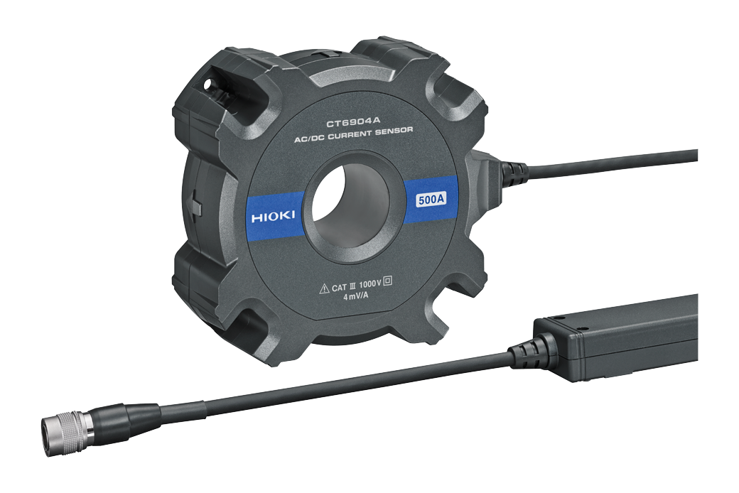
Meeting these requirements calls for the PW8001 Power Analyzer (U7005) paired with the CT6904A Current Sensor. Both instruments offer wideband, flat frequency, and phase characteristics—and, uncommonly for this class of instrumentation, the accuracy of the analyzer and sensor as a combined system is formally specified.
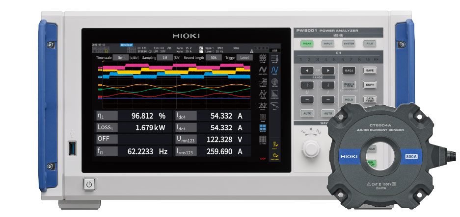 Fig. 5. Hioki's ideal combination of power analyzer PW8001 and current sensor CT6904A.
The figure below shows the phase characteristics of the PW8001 and CT6904A pair compared with those of Company A and Company B. As can be seen, the PW8001 and CT6904A maintain flat phase characteristics over a wide bandwidth.
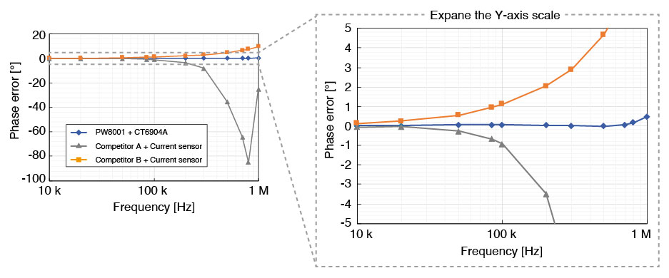 Fig. 6. Phase characteristic comparison.
Effect of Phase Error on Reactor Loss
Loss error [%] is expressed by the following formula.

(1) Perror: Loss error, Φ: Power phase angle, ΔΦ: Phase error
Using Fig. 6 as an example, let us calculate the reactor loss for a sinusoidal wave under the following conditions:
- Apparent power (VI) = 1 kW
- Phase angle Φ = 88°
- Frequency f = 200 kHz
Using the standard formula P = VI cos Φ, the theoretical reactor loss is 34.89 W. However, as Fig. 6 shows, each measurement system exhibits a different phase error (ΔΦ) at 200 kHz. These phase error values are listed in Table I.
Applying each system's ΔΦ to (1) yields the loss error as a percentage, also shown in Table I. The loss error in watts is then obtained by multiplying this percentage by the theoretical value of 34.89 W (for example, Company A: 34.89 W × −174.63% = −60.94 W). Finally, the measured value for each system is calculated by subtracting the loss error (W) from the theoretical value. All of these intermediate and final values are summarized in Table I.
The differences in measured values across the three systems are substantial—demonstrating that the phase error of the measurement system has a significant impact on reactor loss measurement.
TABLE I: Effect of phase error on reactor loss
| Parameter | PW8001 (U7005) CT6904A | Company A | Company B | |
|---|---|---|---|---|
| Phase error ΔΦ | [°] | −0.03 | −3.50 | +2.04 |
| Loss error | [W] | −0.523 | −60.94 | +35.59 |
| [%] | −1.49 | −174.63 | +102.00 | |
| Measured value | [W] | 34.376 | −26.046 | 70.497 |
Experimental Example
A comparative measurement of reactor loss was conducted using two types of current sensors. In this experiment, the CT6872 was used as the comparison target for the CT6904A.
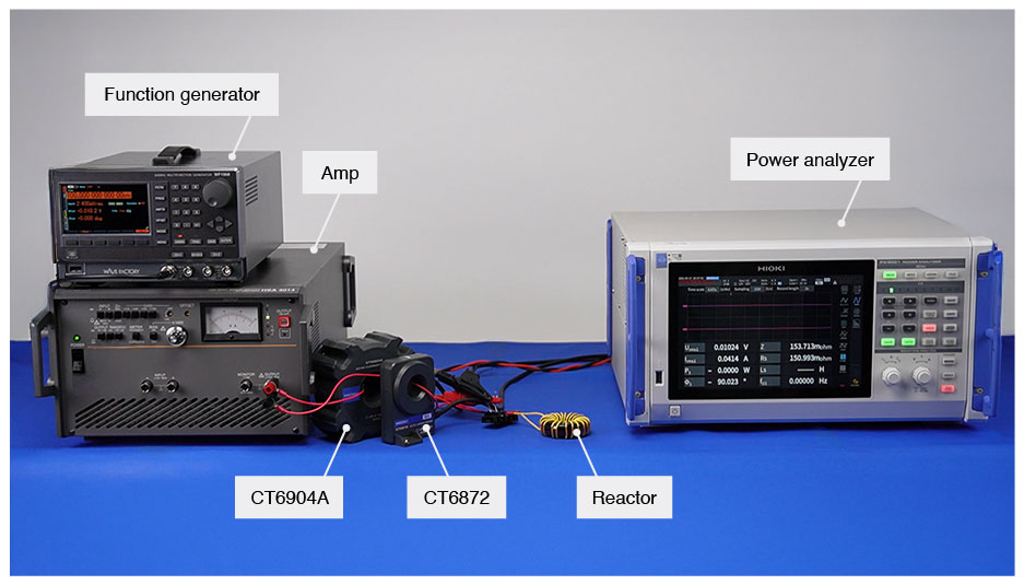 Fig. 7. Experimental setup: equipment configuration for comparative reactor loss measurement using CT6904A and CT6872 current sensors.
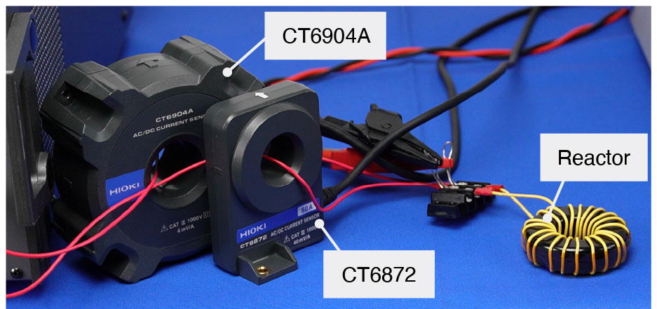 Fig. 8. DUT wiring close-up showing current sensor placement on the reactor under test.
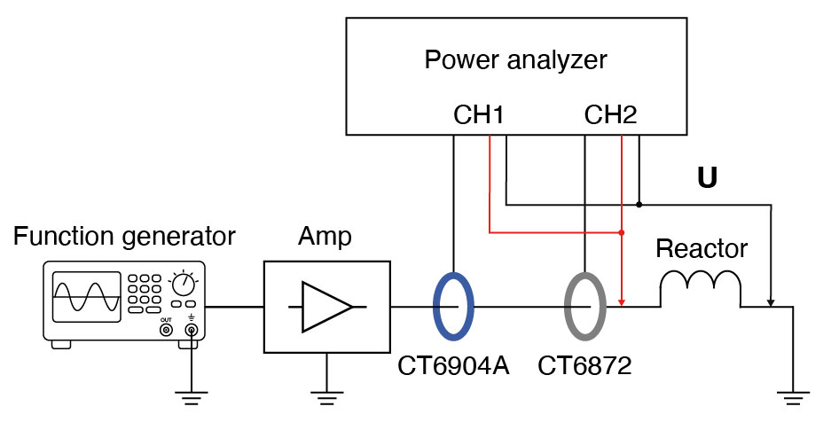 Fig. 9. Block diagram of the experimental measurement system.
Measurement Conditions
- Sinusoidal wave, current approximately 2 A, measured from 100 kHz to 500 kHz in 100 kHz increments
- Data update rate: 200 ms
- Averaging: ON (moving average, 8 samples)
- Sync source: voltage of each channel
- LPF: OFF
- Phase compensation: ON (auto-compensation)
- All other settings: default/identical across both channels
Measurement Results
The graphs below show how active power (reactor loss) and phase angle vary with frequency for a sine wave swept from 100 kHz to 500 kHz. Fig. 10 plots active power; Fig. 11 plots phase angle.
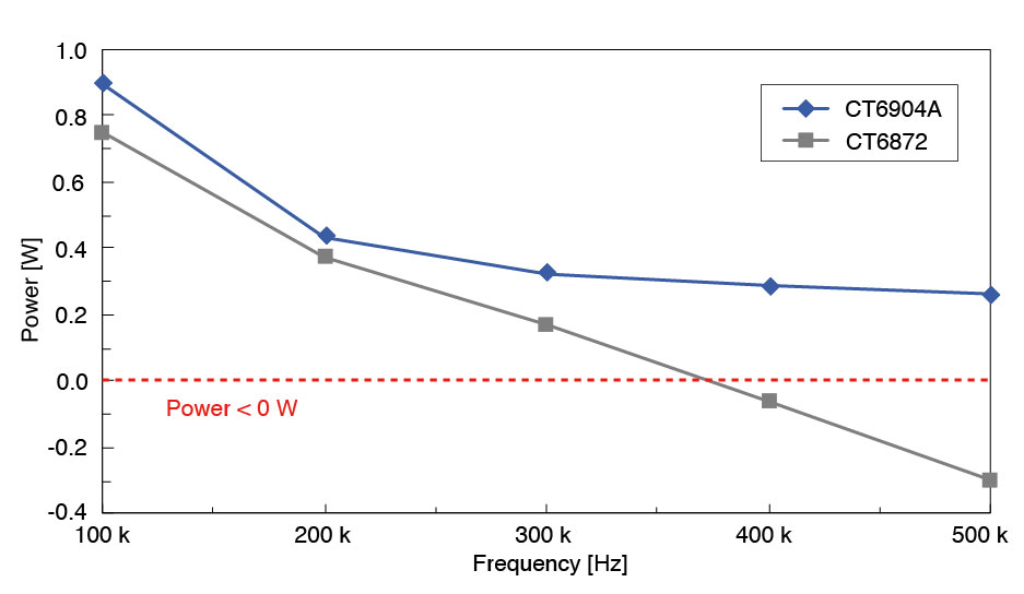 Fig. 10. Active power (reactor loss) versus frequency for CT6904A and CT6872 (100 kHz–500 kHz sine wave sweep).
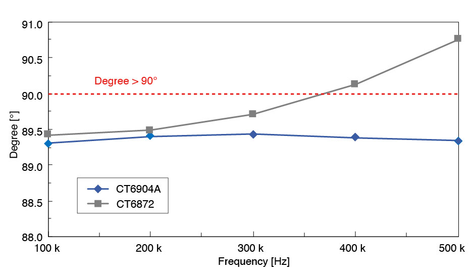 Fig. 11. Power phase angle versus frequency for CT6904A and CT6872 (100 kHz–500 kHz sine wave sweep).
As the frequency of the applied current was gradually increased from 100 kHz, the CT6872 showed a power phase angle exceeding 90° at 400 kHz, resulting in negative power readings. In contrast, the CT6904A maintained a power phase angle below 90° and provided stable measurements throughout. This is attributable to the sensors' different phase characteristics at high frequencies.
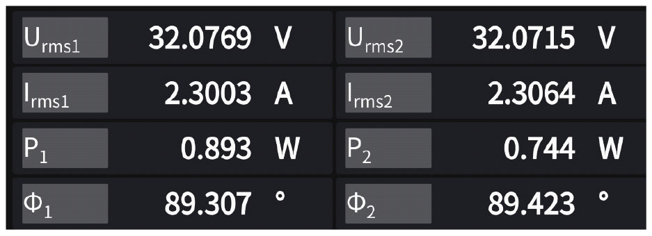 Fig. 12. PW8001 display showing reactor loss measurement at 100 kHz sine wave (CH1: CT6904A, CH2: CT6872).
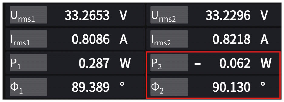 Fig. 13. PW8001 display showing reactor loss measurement at 400 kHz sine wave (CH1: CT6904A, CH2: CT6872).
The CT6872 has wider amplitude bandwidth than the CT6904A; however, its phase characteristics at high frequencies make it less suitable for reactor loss measurement. Therefore, the choice of analyzer and current sensor must be guided by phase characteristics, not amplitude bandwidth alone.
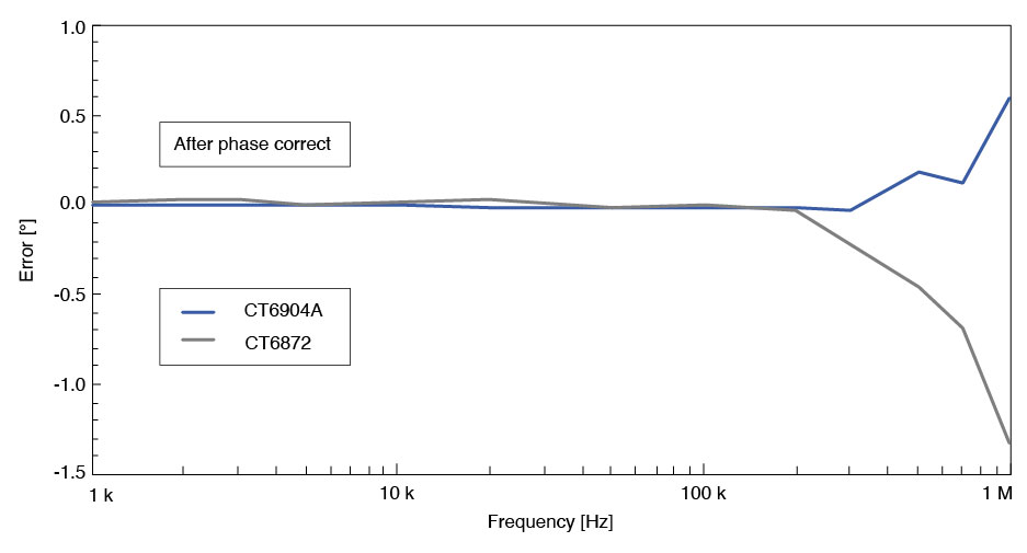 Fig. 14. Phase characteristics comparison of CT6904A and CT6872 current sensors across frequency.
Especially in the case of actual circuit measurements, such as interleaved PFC, various high-frequency components—including the switching frequency—are superimposed. This means that differences in instrument performance, including phase characteristics, have a significant impact on the measured loss values. As a result, the gap between instruments widens substantially—making instrument selection even more critical for real-world circuit measurements than for clean sine-wave testing.
For lower-current applications (50 A or below), the PW9100A—a direct-connection current input module for the power analyzers—can replace the CT6904A clamp-on sensor. It delivers equivalent phase characteristics, preserving measurement accuracy.
Equipment List
| PW8001 | ×1 | Power analyzer | |
| U7005 | ×2 | Input unit | 15 MS/s, 18 bit, DC to 5 MHz |
| CT6904A | ×1 | Current sensor (CH1) 500 A rating | Amplitude: DC to 4 MHz Phase: DC to 1 MHz |
| CT6872 | ×1 | Current sensor (CH2) 50 A rating | Amplitude: DC to 10 MHz Phase: DC to 1 MHz |
DUT
| Function generator | ×1 | NF CORPORATION |
| Amplifier | ×1 | NF CORPORATION |
| Reactor | ×1 | — |
Conclusion
Accurately measuring and understanding reactor losses is essential for design optimization, efficiency improvement, and achieving higher-performing power supplies. Because reactors exhibit level dependency, measurements must be performed under actual operating conditions using a power analyzer.
Moreover, since such measurements involve high-frequency, low-power-factor conditions, the phase characteristics of the measurement instruments have a significant impact on the accuracy of results. To achieve accurate measurements that account for phase error, it is critical to select the appropriate combination of power analyzer and current sensor.
If you have any questions about this application note or measurements, please feel free to contact us.
Related Resources
- Measurement Errors Exceeding 10%!? The Key Role of Current Sensors in Accurate SiC/GaN Inverter Efficiency Evaluation
- Measurement of Loss in High-Frequency Reactors
- Real Operating Loss Measurement of Low-Loss Inductors Using High-Precision Wideband Power Analyzer and Current Sensor
- Measurement of Loss in Inductors and Transformers in xEV Power Supplies
- Effectiveness of Current Sensor Phase Shift When Evaluating the Efficiency of High-efficiency Motor Drives