Measurement Errors Exceeding 10%!? The Key Role of Current Sensors in Accurate SiC/GaN Inverter Efficiency Evaluation
Adoption of SiC and GaN devices in power electronics devices is accelerating as the effective use of energy becomes increasingly important. In the development of high-efficiency SiC and GaN devices, it is essential to evaluate power conversion efficiency improvements with an accuracy of 0.1% to measure efficiency higher than 99%.
This application note introduces measurement comparisons that were made to observe the influence of current sensors on SiC/GaN inverters. In this experiment, an SiC inverter's output power was made using current sensor models from Hioki and one of Hioki's competitors. The data showed that the discrepancy between measurements increased in proportion to the switching frequency (characteristically high for SiC and GaN inverters). In some cases, the differences exceeded 10%. Why did such significant discrepancies occur in an application where accuracy of 0.1% is required? Which current sensor's measurement should be trusted?
This Application Note explores the observed measurement results and introduces key considerations when selecting current sensors for measuring inverter efficiency.
1. Issue
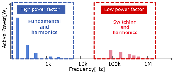
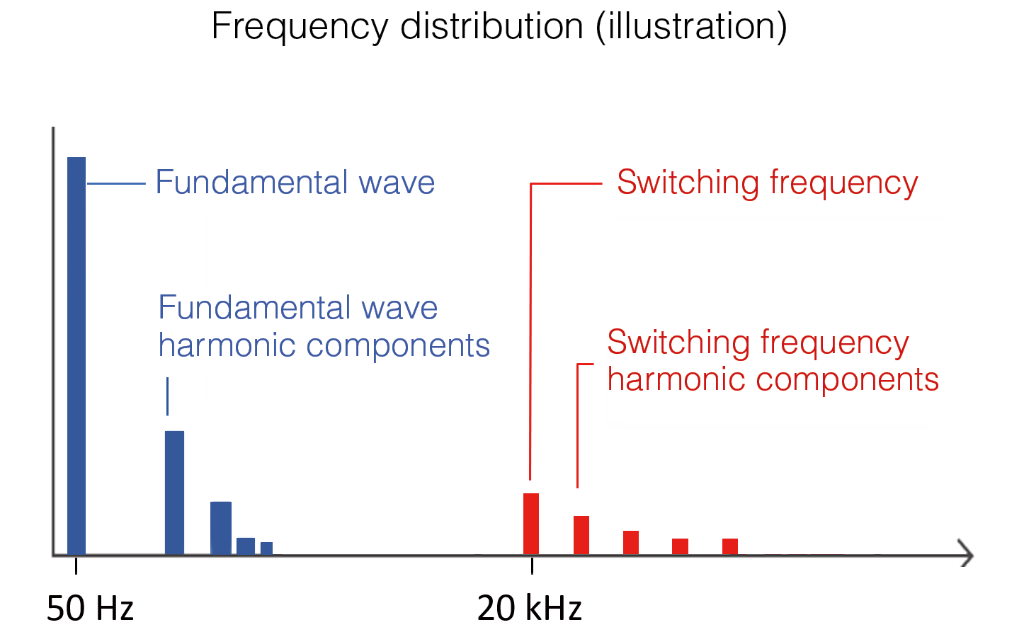
As seen in the power spectrum analysis below, power output from inverters includes the fundamental frequency component driving the motor and its harmonics (shown in blue) as well as the inverter’s switching frequency and its harmonic components (shown in red). The fundamental wave and its harmonic components are in the low-frequency range (typically a few kilohertz) and can be measured relatively accurately using conventional power analyzers and current sensors. However, the switching frequency and their harmonic components fall in the high-frequency range (tens of kilohertz to several megahertz) and exhibit low power factors. This high frequency band requires broadband power analyzers and current sensors capable of high-precision phase measurement. Inability to accurately measure high-frequency power, consisting of switching frequencies and their harmonic components, may lead to issues such as measurement variability, efficiency in excess of 100%, or significant deviations from the theoretical power loss values.
Key considerations in high-frequency measurement
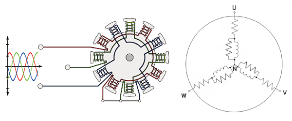
Motor equivalent circuit
The motor equivalent circuit consists of a resistors and inductors. At high frequencies (above several tens of kHz), the impedance caused by inductive components becomes high, resulting in a low power factor. Consequently, a broadband measuring instrument capable of accurately measuring inverter carrier frequencies and beyond is required.
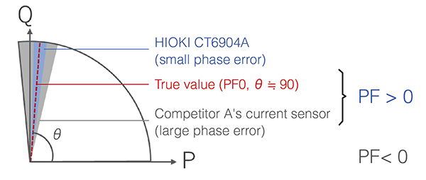
Characteristics of low-power-factor measurement
In low-power-factor measurement, the phase difference between voltage and current approaches 90°, and even a slight phase shift can result in significant measurement error. When using a measuring instrument with large phase error, the phase difference may exceed 90°.
2. Comparison of inverter output measurements
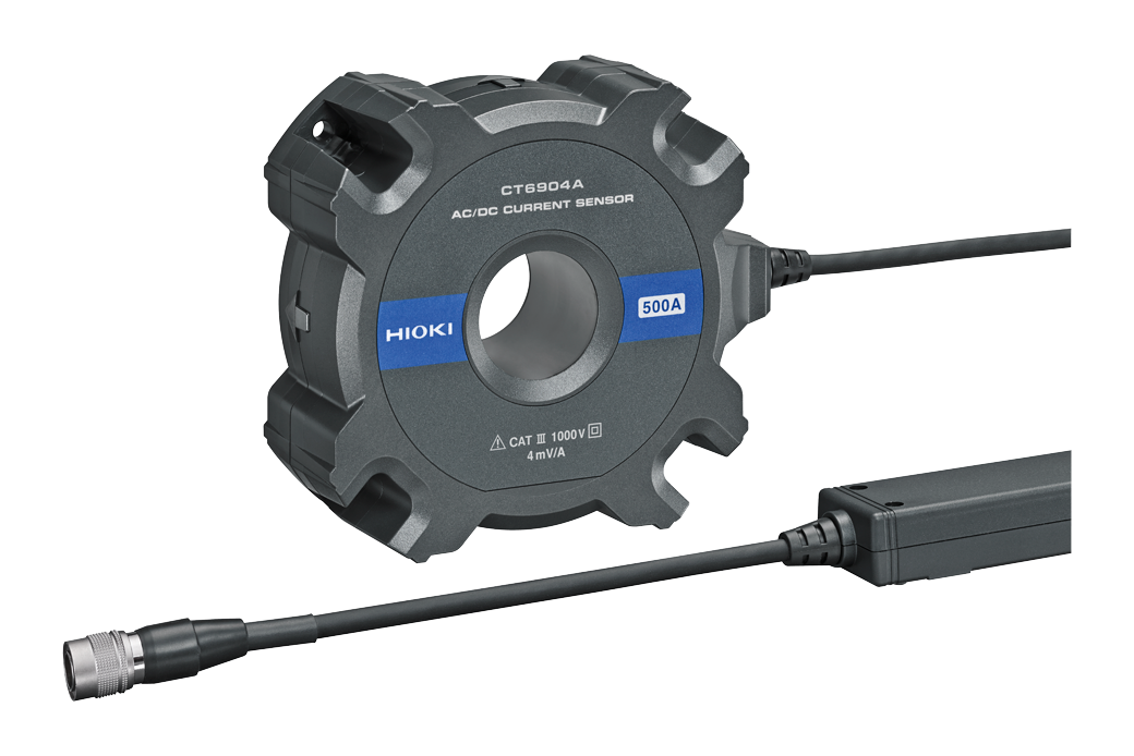
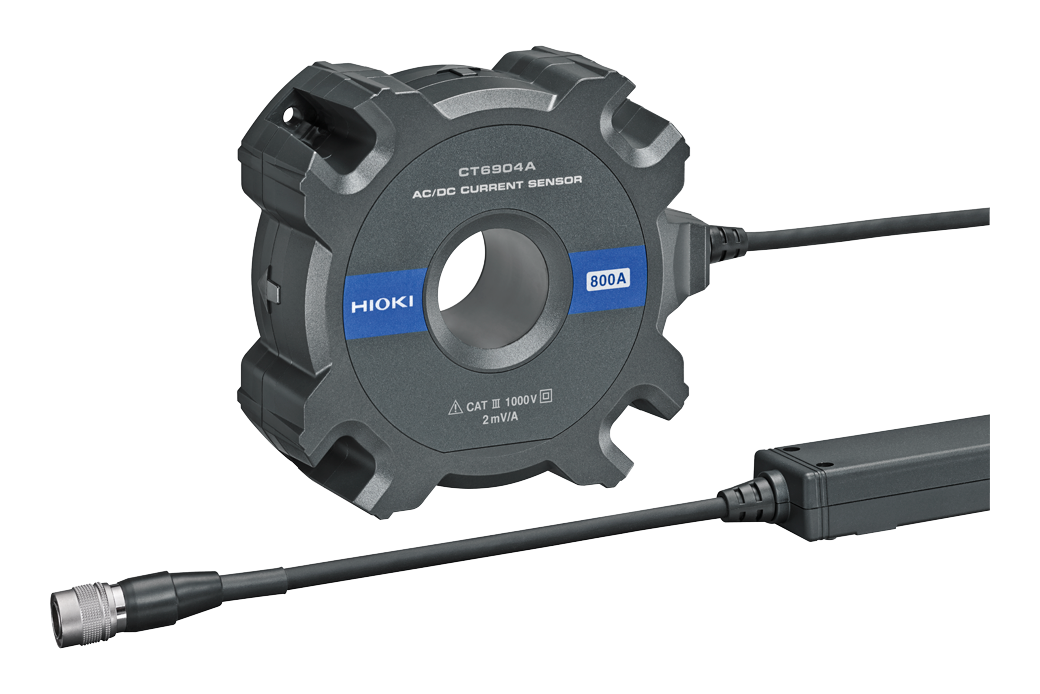
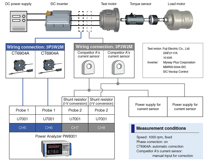
We conducted a comparison of measurements using the high-end PW8001 Power Analyzer as the primary instrument. The comparison was done between the CT6904A Current Sensor, which features excellent phase characteristics, and a current sensor of one of Hioki's competitors (referred to as "Competitor A"). Competitor A's current sensor is a current-output-type current sensor—a sensor representative of the market standard—with a comparable current rating (1000 A), but with a bandwidth of up to 300 kHz. We kept measurement conditions, including wiring, identical. We examined how differences in phase characteristics affected high-frequency power measurements.
Block diagram of the measurement setup
Impact of current sensor characteristics on active power measurement

The frequency distribution of active power in inverter output can be separated into the fundamental and harmonics of the motor driving frequency and the fundamental and harmonics of the switching frequency. All active power, including the driving fundamental wave, is consumed as energy by the motor, and ideally would appear as positive components on the power analyzer's screen.
However, the power factor decreases in the high-frequency region above 20 kHz. As a result, use of a current sensor with poor phase characteristics can cause active power, which ought to appear as a positive component, to instead appear as a negative component, affecting the measurement results.
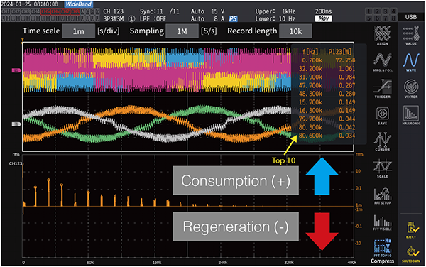
Visualization of power loss with Power Spectrum Analysis (PSA)
The new Power Spectrum Analysis (PSA) function was introduced with the software update Ver. 2 of the PW8001 Power Analyzer. It is essentially FFT analysis, but for power. Traditionally, FFT analysis has focused on analyzing voltage and current, but thanks to the PSA's addition of active power as a new analysis parameter, it is now possible to visualize power distribution across various frequency components. This capability allows users to visually distinguish between power consumption and regeneration in loads.
Related video: “PSA: Analyzing Motor Loss”
https://www.youtube.com/watch?v=WliAbo6rmkc&t=7s&ab_channel=HiokiE.E.Corporation
Function introduction: Investigating inverter motor loss using power spectrum analysis (PSA) functionality https://www.hioki.com/us-en/learning/applications/detail/id_n1266683
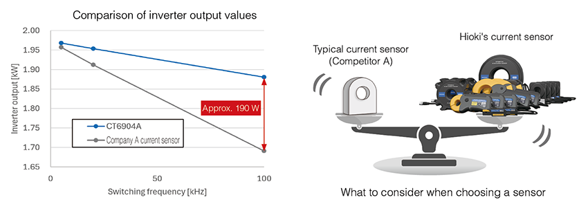
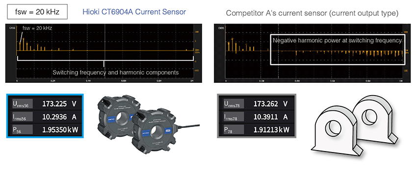
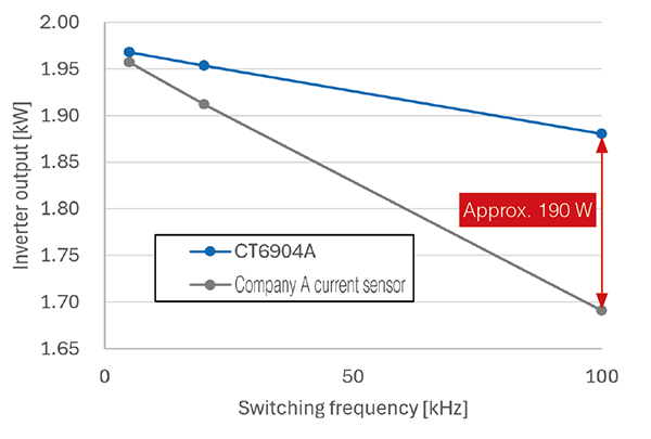
Comparison results
At a switching frequency of 20 kHz, active power measurement showed a discrepancy of approximately 40 W (about 2.1%). The PSA function can be used to analyze the reason for this difference. Measurements taken with the Hioki CT6904A current sensor show all active power, including the switching frequency and its harmonic components, as positive (consumed power). By contrast, the measurement of high-frequency power at the switching frequency and its harmonic components using Competitor A's current sensor are incorrectly displayed as negative (regenerated power). Based on this, we can conclude that the measurements from the Hioki CT6904A are more reliable. The discrepancy arises due to differences in the phase characteristics of the current sensors.
If the switching frequency is increased further
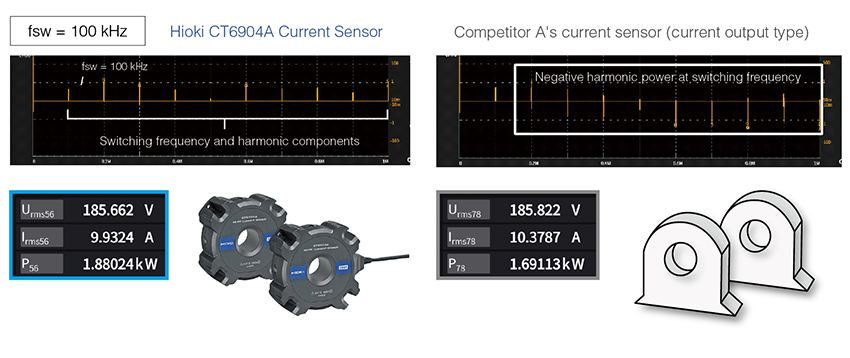
When the switching frequency was increased to 100 kHz, a difference of approximately 190 W (about 10%) in active power was observed. Using the PSA function, it was confirmed that the current sensor from Competitor A showed negative power in the high-frequency range starting at around 200 kHz (twice the switching frequency), indicating that its measurements stopped being accurate due to switching frequency's harmonic components .
Comparison of errors in inverter output active power
As the switching frequency increased, the difference in active power between the two measurements became more significant. In general, use of SiC/GaN in inverters and their increase in switching frequency is expected to improve efficiency and enable downsizing and weight reduction. As such, since these differences can have a significant impact on accurate measurement, development of SiC/GaN inverters requires careful consideration of the phase characteristics of current sensors. In short, selecting the appropriate current sensor is crucial in order to ensure reliable measurement.
Comparison of inverter output values
Measurements in a typical hybrid automobile
100W loss reduction≒ 2 km/L fuel efficiency improvement

For example, in the development of inverters for automotive applications, engineers seek to manage heat in increments as small as 10 W to achieve better power consumption efficiency and reduced charging times. Consequently, the accuracy required from measurement instruments continues to increase.
3. Solution from Hioki
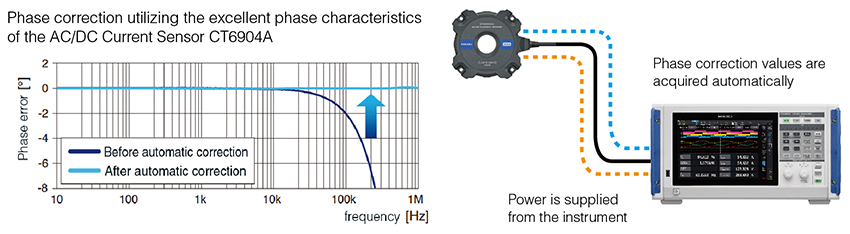
Hioki not only guarantees excellent performance for broadband measurements by both power analyzers and current sensors on a standalone basis, but also specifies phase error when these devices are used in combination. Furthermore, the PW8001 features an automatic phase correction function, enabling wide-range phase correction and providing robust support for high-accuracy measurements under low-power-factor conditions. This makes Hioki's power analyzers and current sensors ideal for measuring efficiency and loss of high-efficiency SiC/GaN inverters and the high-efficiency motors paired with them.
In conclusion, the accurate measurement of inverter efficiency in SiC and GaN devices is critical for advancing development of inverters. The discrepancies between current sensors for higher frequency power associated with these inverters highlight the importance of selecting sensors with superior phase characteristics. This application note illuminated Hioki's CT6904A current sensor as superior in this way to its competitor, representative of other similar sensors on the market. As the demand for power conversion approaching and even exceeding 99% continues to grow, engineers must prioritize the use of sensors and power analyzers with the proper phase characteristics and accuracy to effectively measure power. Just as in this case with Hioki's CT6904A AC/DC Current Sensor and PW8001 Power Analyzer, Hioki is committed to providing solutions that ensure accurate and practical measurement for engineers throughout the world.
For more information about Hioki's current sensors, power analyzers, or other solutions, please browse Hioki's website or contact the salesperson best suited for your situation from our contact page. https://www.hioki.com/contact