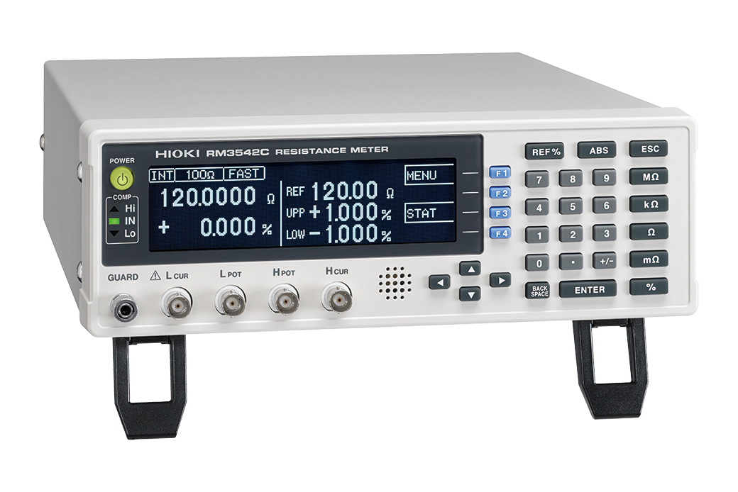
RESISTANCE METER RM3542C
High-precision resistance meter for automated in-line testing of chip resistors and ferrite beads


NEW
-

-
 RM3542C-2
 -
-

Optimize automation and quality for next-generation production testing
The RM3542C is a DC resistance meter for automated in-line inspection of chip resistors and ferrite beads. On-instrument ΔR compares process-to-process change, while BIN grading (up to 7 bins) delivers instant pass/fail and ranking. Jumper-resistor assist speeds low-resistance screening. ≤5 V low-stress measurement and continuous contact monitoring secure reliability. Optimized ranges and a galvanic isolation architecture keep results stable on noisy lines, enabling stricter inspection with higher throughput.
Key Features
- ΔR Function (process comparison)
RM3542C-3 only - BIN grading (sorting)
RM3542C-3 only - Jumper Resistance Measurement Support
- Takt time× repeatability
- Low-stress testing
- Noise immunity
Model No. (Order Code)
| RM3542C-1 | Standard model |
|---|---|
| RM3542C-2 | Standard model (GP-IB compatible) |
| RM3542C-3 | Advanced model |
Three Benefits of Smart Testing
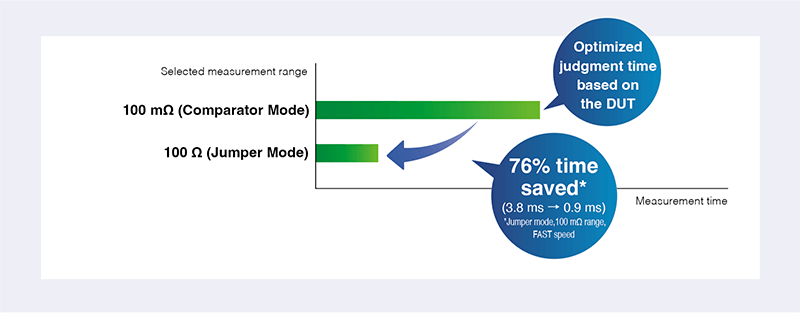
Shorten jumper resistor inspection time by up to 76%
Jumper Resistance Measurement Support (Jumper Mode) skips the slower, high-accuracy measurement ranges at or below 100 mΩ, shortening inspection time by 76%. Keeps your production throughput high.
Example: inspect a 100 mΩ jumper resistor (zero-ohm resistor) with comparator limits set to 100 mΩ (upper limit) and 50 mΩ (lower limit).
Instrumentʼs settings
Measurement speed: fast, Delay 2 (time between application start and measurement): 0 ms
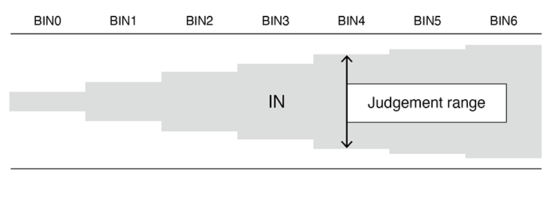
Improve grading and sorting efficiency (RM3542C-3 only)
BIN Measurement performs judgments and automatic grading into 0-6 categories (up to 7 bins). Reduces system workload and repose time, improving efficiency on production lines with strict takt time requirements.
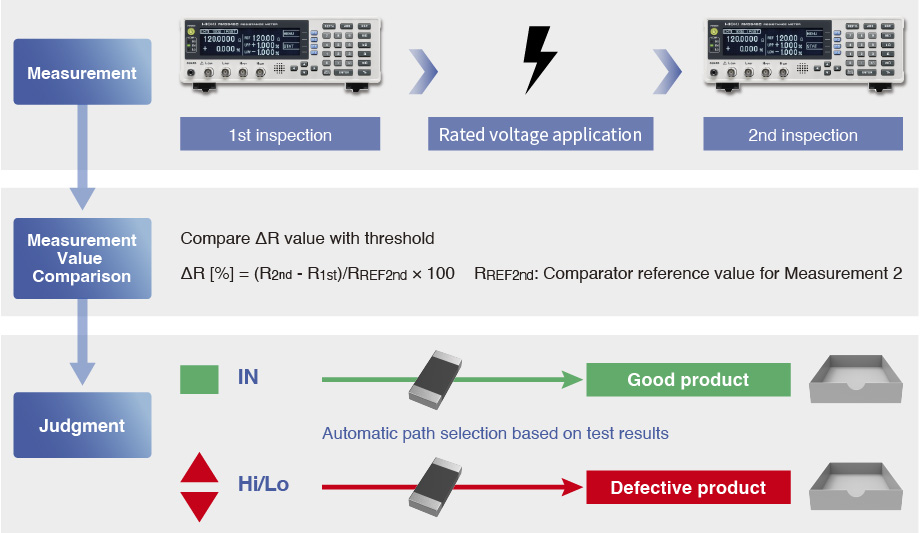
Increase inspection reliability and overall taping machine efficiency (RM3542C-3 only)
ΔR Function (cross-stage auto-judgment) automatically compares measurement results from two separate instruments and flags defects when the difference exceeds a threshold. This strengthens inspection reliability and reduces system workload by eliminating manual cross-checks
Meet Speed / Repeatability Requirements of Your Production Line.
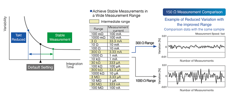
Optimized integration time and range
Integration Time Control lets you assign an integration time to each measurement range to match your production needs—from Fast mode down to 0.9 ms for short takt-time, high-throughput lines, to Slow mode for maximum stability and repeatability. Optimized intermediate ranges (e.g., 3 and 300 Ω) boost S/N ratio, cut variation, and ensure repeatable results. A galvanically isolated architecture minimizes the effect of external electrical interference, delivering stable data in high noise production lines.
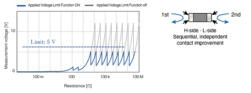
Avoid damaging delicate devices
Limit applied voltage to 5 V or less (Applied Voltage Limit) to enable safe and accurate testing of micro-components such as 0080004 size resistor. Applying Contact Improvement sequentially to H and L sides suppresses inrush current —preventing characteristics shifts in sensitive parts like ferrite beads.
Operating conditions: set Contact Improvement to “Pulse” and turn on either Low-power Resistance Measurement or Applied Voltage Limiter.
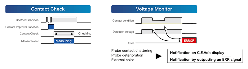
Eliminate contact errors
Pre-measurement Contact Improvement (17/25/35/50 mA) stabilizes the probe contact. Continuous Contact Check and Voltage Monitor reduce contact-related misjudgments and the risk of line stoppage.
Smart Functions for Enhanced Precision
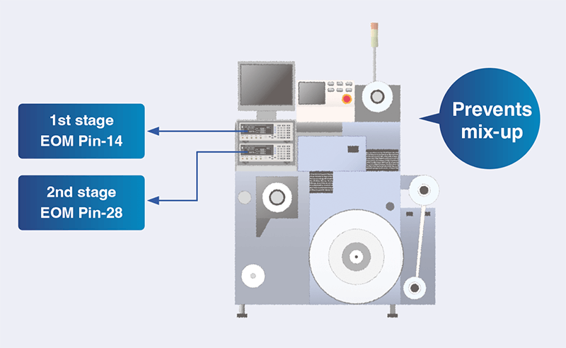
Preset instantly recalls saved conditions to prevent operator setup errors and keep measurement conditions consistent on multi-product lines. Stage Mismatch Prevention avoids miswiring after calibration or maintenance on dual-meter automated equipment. 90-Day Accuracy* delivers higher measurement accuracy for ultra-tight-tolerance components compared to standard 1-year accuracy—achieving setup repeatability, line stability, and rigorous pass/fail decisions simultaneously. *RM3542C-3 only.
Basic specifications
| Resistance range | [at Low Power OFF] 100 mΩ range (Max. 120.0000 mΩ, 0.1 μΩ* resolution) to 100 MΩ range (Max. 120.0000 MΩ, 100 Ω resolution), 16 steps *Additional range for RM3542C-3: 10 mΩ (Max. 12.00000 mΩ, 0.01 μΩ resolution) [at Low Power ON] 1000 mΩ range (Max. 1200.000 mΩ, 1 μΩ resolution) to 1000 Ω range (Max. 1200.000 Ω, 1 mΩ resolution), 6 steps |
|||||
|---|---|---|---|---|---|---|
| Display | Monochrome graphic LCD 240 × 64 dot, white LED backlight | |||||
| Measurement accuracy | [with SLOW mode, at 100 mΩ range] ±0.015 % rdg. ±0.002 % f.s. [with SLOW mode, at 1000 Ω range] ±0.006 % rdg. ±0.001 % f.s. 90-day accuracy (RM3542C-3 only) [with SLOW mode, at 100 mΩ range] ±0.012 % rdg. ±0.002 % f.s. [with SLOW mode, at 1000 Ω range] ±0.005 % rdg. ±0.001 % f.s. |
|||||
| Testing current | [at 100 mΩ range] 100 mA DC to [at 100 MΩ range] 100 nA DC | |||||
| Open-terminal voltage | 20 V DC max. (with applied voltage limit function enabled: max. 5 V DC) | |||||
| Sampling rate | FAST, MEDIUM, SLOW, 3 settings | |||||
| Measurement times | [at 100 Ω /300 Ω/1000 Ω ranges, with Low Power OFF] FAST: 0.9 ms, MED: 3.6 ms, SLOW: 17 ms (minimum time) |
|||||
| Integration time | 0.1 ms to 100.0 ms, or 1 to 5 PLC at 50 Hz, 1 to 6 PLC at 60 Hz Note: PLC = one power line cycle (mains wave-form period) |
|||||
| Other functions | Comparator (set-value vs. measured-value comparison), BIN Measurement (RM3542C-3), Low-power Resistance Measurement, Delay Setting, Offset Voltage Compensation (OVC), Integration Time Setting, Average (RM3542C-3), Faulty Measurement Detection, Probe Short-Circuit Detection, Contact Improvement, Current Mode Setting, Stage Mismatch Prevention, Scaling, Retry, Applied Voltage Limiter Function, Jumper Resistance Measurement Support, Preset, ΔR (RM3542C-3), Memory, Statistical Calculation, Settings Monitor, Trigger Source Setting, Printer Function | |||||
| Interfaces | RS-232C, Printer (RM-232C), GP-IB (Model RM3542C-2) | |||||
| External I/O | Trigger, Hold input, Comparator output and other, Settings monitor terminal | |||||
| Power supply | 100 to 240 V AC, 50/60 Hz, 30 VA max. | |||||
| Dimensions and mass | 260 mm (10.24 in) W × 88 mm (3.46 in) H × 300 mm (11.81 in) D, 2.9 kg (102.3 oz) | |||||
| Included accessories | Power cord ×1, EXT. I/O male connector ×1, Instruction manual ×1, Operation guide ×1 | |||||
Probe and Test fixtures (4)
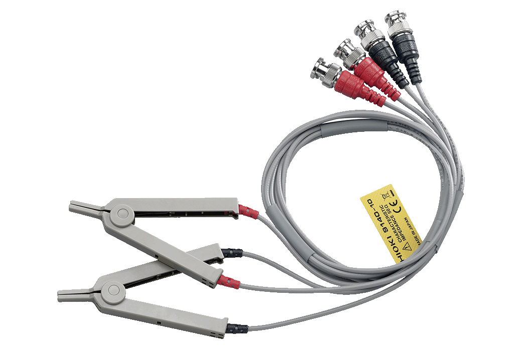
Cable length 1 m (3.28 ft), DC to 200 kHz, impedance characteristics of 50 Ω, 4-terminal pair configuration, measurable conductor diameter: ø0.3 (0.01 in) to 5 mm (0.20 in)
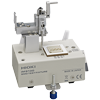
Direct connection type, DC to 8 MHz, measurable conductor diameter: ø0.3 (0.01 in) to 2 mm (0.08 in)

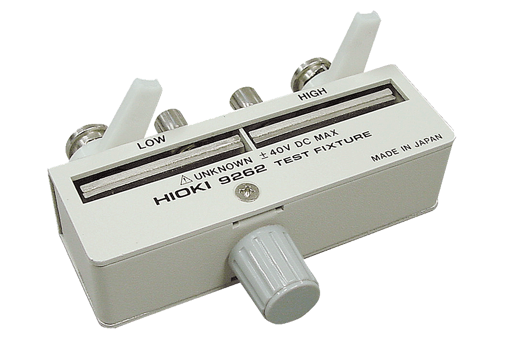
Direct connection type, DC to 8 MHz, Test sample dimensions: 1 mm (0.04 in) to 10 mm (0.39 in)
PC communication (2)
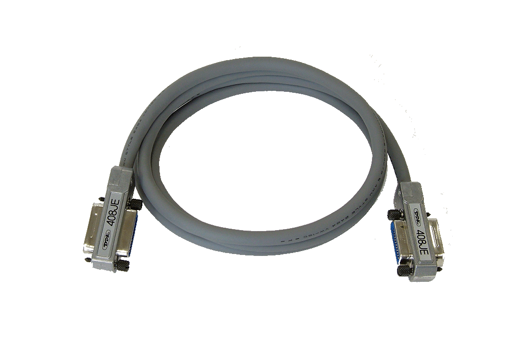
2 m (6.56 ft) length
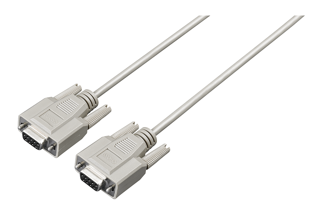
9 pin - 9 pin, cross, 1.8 m (5.91 ft) length
Replacement Parts (3)
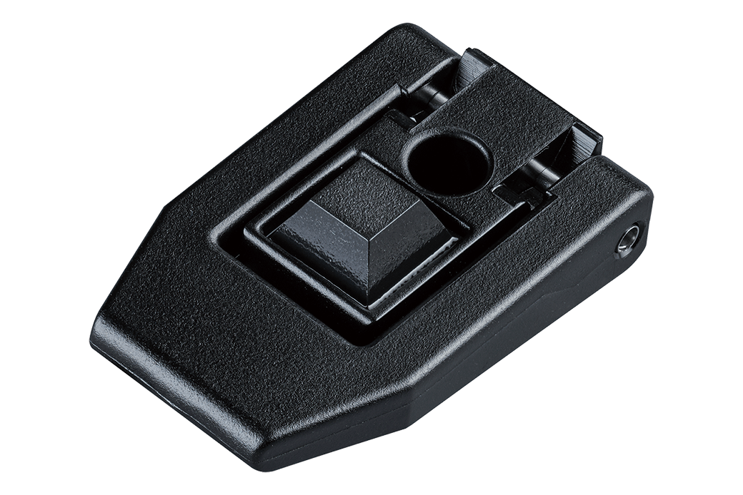
Order Code: Z7052
Single piece
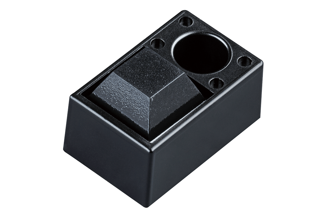
Order Code: Z7053
Single piece
Order Code: Z7054
-
RESISTANCE METER RM3542C-3
 Test Report
Japanese
Test Report
Japanese
English Ver.01 -
RESISTANCE METER RM3542C-2
Test Report
Japanese
English Ver.01 -
RESISTANCE METER RM3542C-1
Test Report
Japanese
English Ver.01 -
RESISTANCE METER RM3542C
Instruction Manual
Simplified Chinese
Ver.00
-
RESISTANCE METER RM3542C
Instruction Manual
English
Ver.00
-
RESISTANCE METER RM3542C
Startup Guide
English
Ver.00
-
RESISTANCE METER RM3542C
Startup Guide
Korean
Ver.00
-
RESISTANCE METER RM3542C
Startup Guide
Simplified Chinese
Ver.00