Comparison of SiC Inverters Measured by High-end Power Analyzers
Introduction
In recent years, research and development has driven advancement in inverters utilizing high-speed switching in order to increase power conversion efficiency). Power semiconductors such as SiC and GaN enable the faster switching of inverters. This high efficiency also results in the miniaturization of smoothing coils, capacitors, and other components. Furthermore, the reduction of power loss during switching (a.k.a. switching loss) allows heat sinks and other heat dissipation components to be miniaturized. As a result, the inverter and motor as a whole can be made more efficient, smaller, and lighter.
However, with the increase in switching speeds, there arises a need for wider bandwidth and even more accurate power measurement than ever before, so the selection of an appropriate measurement device is very important. In this application note, we introduce the results of a measurement comparison of a SiC inverter’s efficiency using Hioki's PW8001 power analyzer and another high-end power analyzer from Competitor A.
Effect of measurement error on inverter output power
The solution to improving inverter and motor efficiency and reducing their size and weight as of now has been to increase the switching frequency. However, increased switching frequency also makes it difficult to accurately measure the output power of the inverters.
For example, in the development of inverters in automobiles, thermal management is performed in increments of 10 W with the aim of improving efficiency and shortening charging time. By accurately measuring inverter and motor losses, it is possible to perform optimal thermal management designs.
If measurement error is large and the loss is mistakenly assumed to be larger than the actual loss, excessive thermal management such as additional insulation or parts would be added to the design. In this way low accuracy in inverter power efficiency measurement frustrates efforts toward miniaturization and weight reduction.

Comparison of Efficiency Measurement of SiC Inverters and Motors
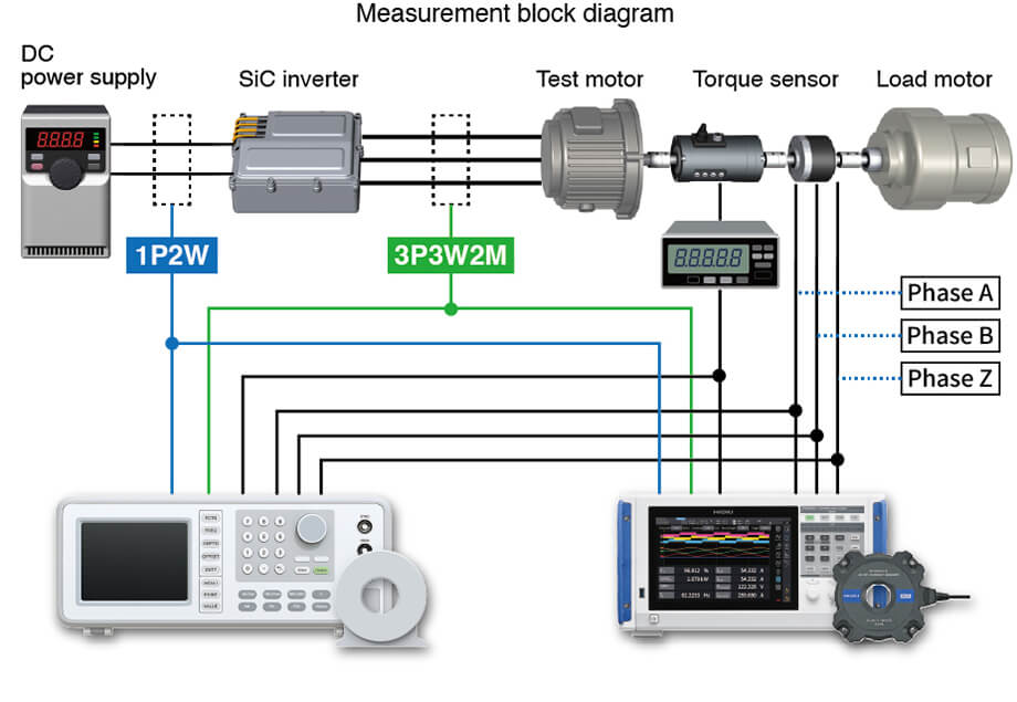
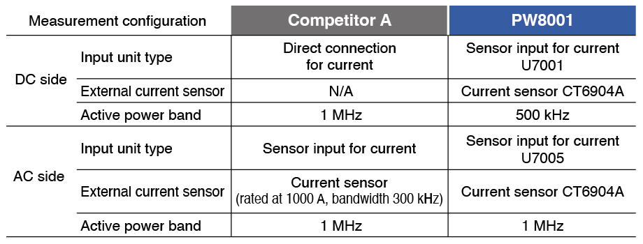
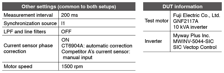
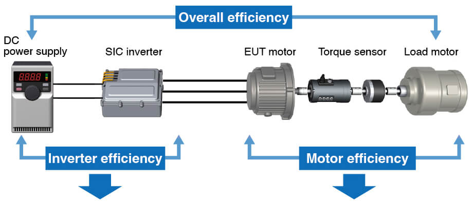
The block diagram below shows a measurement comparison of a SiC inverter's power conversion. Three parameters were measured, the input power of the inverter (1P2W), the output power of the inverter (3P3W2M), and the motor power. Measurements were made simultaneously by two types of power analyzers. In addition, since the PW8001 measures using AC/DC current sensors (model CT6904A), measurements by Competitor A's power analyzer were also performed with a similar current sensor from Company A for the purpose of aligning the test conditions.
Comparison of Inverter Efficiency, Motor Efficiency, and Overall Efficiency
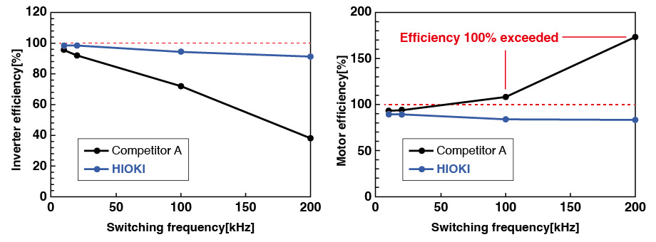
In this experiment, the switching frequency of a SiC inverter was set to vary between 10, 20, 100, and 200 kHz. The inverter efficiency and motor efficiency were measured. Looking at the inverter efficiency comparison, one can observe that the difference between the two models increases with the switching frequency. In addition, the comparison of the motor efficiency shows that not only did the difference increase with the increase in switching frequency, but the efficiency of the Competitor A’s power analyzer exceeded 100%—a practical impossibility.
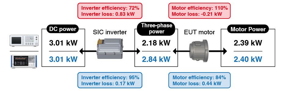
The following figure compares the inverter, motor, and total efficiency at a switching frequency of 100 kHz. The data shows that there is no significant difference between the DC power, which is the input of the inverter, and the motor power calculated from the torque gauge and encoder. However, there is a large difference in the measurement of the three-phase power, which is the inverter output.
For example, if we look at the inverter loss, the PW8001 measurements show a loss of 0.17 kW, while the power analyzer of Competitor A shows a loss of 0.83 kW.
If loss is overestimated, unnecessary measures will be taken such as designing extra functions to dissipate heat and redesigning controls.
Criteria for selecting a power analyzer to accurately measure power of a fast switching inverter
Features of inverter output power
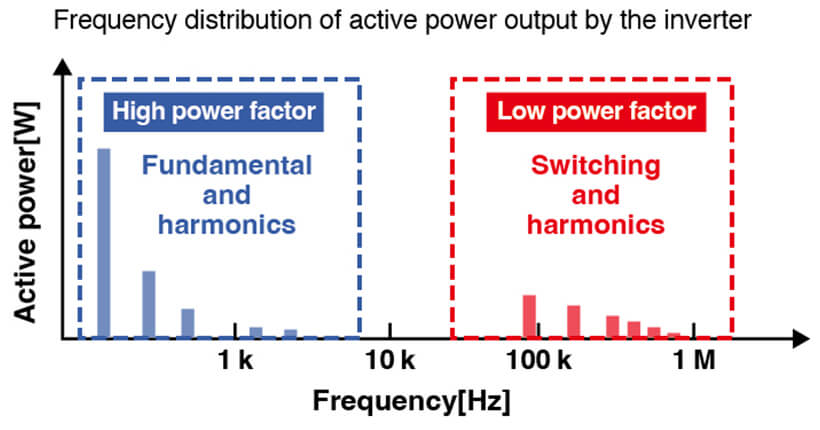
Why was there a difference in active power? The following figure shows the frequency distribution of active power output by the inverter measured by Hioki's PW8001. The output power of the inverter includes the fundamental frequency component that drives the motor and its harmonics (blue part), as well as the switching frequency of the inverter and its harmonics (red part). As the frequency distribution shows, active power is distributed over a wide range from low to high frequencies, so a power analyzer that supports a wide band is essential to accurately measure the output power of an inverter.
In addition, since the switching frequency and its harmonic component in the output power of the inverter have a low power factor, it is necessary to accurately capture the phase difference between the output voltage and the output current including the high frequency range.
The Importance of phase accuracy
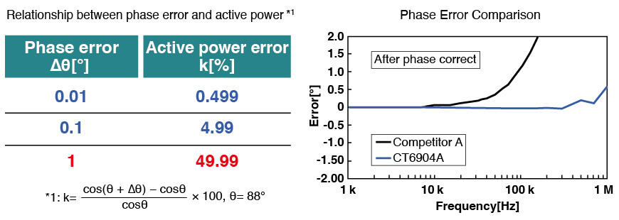
In order to correctly measure the inverter output power, it is especially important to be able to correctly measure the switching frequency and its harmonic content. Phase error has a significant impact on the measurement of active power, especially at low power factors (voltage and current phase difference of 90°). For example, if the phase error of the instrument is 1° for a phase of 88°, the error when converted to active power is about 50%. In this way, the measuring instrument must be able to accurately measure high frequencies which have a low power factor.
Hioki has developed high-precision current sensors in-house, and since we strictly control the phase characteristics of each sensor model, we are able to achieve phase correction over a wide bandwidth.
For example, when comparing the phase error of 100 kHz, the current sensor of Competitor A has a phase difference of more than 1.0°, while the error of the HIOKI CT6904A is less than 0.01°.
Summary
Using high-end power analyzers, we conducted a comparison of SiC inverter measurements. There was a clear difference in the measured inverter output power between Hioki’s and the competitor’s power analyzer. With the Hioki PW8001, which can accurately measure up to harmonic switching frequencies, we observed losses in those high frequencies that were unnoticed by the competing analyzer. Through this experiment, it can be concluded that the Hioki device is more reliable.
Since SiC inverters have a low power factor in the output power of their switching frequency and resulting harmonic components, it is important to select a power analyzer and current sensor with a wide bandwidth and good phase accuracy. In the market, Hioki is the only supplier that provides this with combined accuracy of the current sensor and power analyzer, making it the best choice for efficiency measurements of high-speed switching inverters.