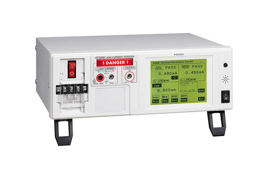
LEAK CURRENT HiTESTER ST5541
Leak Current Measurement, an Essential Part of Electrical Safety
(for electrical devices)

To Be Discontinued
To ensure the safe use of electrical products, electrical safety tests such as insulation resistance, withstand voltage, ground resistance, and leakage current must always be conducted. Hioki Leakage Current Testers comply with laws and standards regarding medical electrical equipment as well as non-medical electrical equipment, and can be used to measure leakage current in all types of electrical products from computers to medical equipment.
The ST5541 provides support for standard-compliant networks (excluding medical-use electrical devices).
Key Features
- Compliance with Electrical Appliances and Materials Safety Act, JIS/IEC/UL standards
- Uninterrupted polarity switching function dramatically reduces cycle time
- Support for rated currents up to 20 A gives the instrument more than adequate capability for testing products designed to comply with new standards
- Touch panel features simple, interactive operation
- Communications functionality and external I/O support allow automatic testing on production lines
Model No. (Order Code)
| ST5541 | For electrical devices |
|---|
For Standard- and Regulation-compliance Measurement of General-use Electrical Devices
There are various standards in place concerning networks (body simulated resistance), and a standard-compliant network is required in order to make measurements.
ST5541 provides standard support for standard-compliant networks (excluding medical-use electrical devices).
Basic specifications
| Measurement methods | Measurement of voltage drop across body simulated resistance points, Calculation and display of current values, True rms measurement, Measurement unit floats relative to instrument ground. | |||||
|---|---|---|---|---|---|---|
| Measurement modes | Leak current measurement, voltage measurement, safety conductor current measurement | |||||
| Standards compliance (NW: Body simulated resistance) |
[NW-A] • Electrical Appliances and Materials Safety Act [NW-C] • Measurement of touch current and protective conductor current: IEC 60990:2016 • Electrical equipment for measurement, control, and laboratory use: IEC 61010-1:2010+ A1:2016 • Information technology equipment: IEC60950-1:2005+ A1:2009+ A2:2013 • Audio, video and similar electronic apparatus: IEC 60065:2014 • Personnel Protection Systems for EV: UL 2231-1:2012 (Amended 2016), UL-2231-2:2012 (Amended 2016) [NW-D] • For UL: UL 1492:1996 (Amended 2013) [NW-G] • Electrical equipment for measurement, control, and laboratory use; current measurement circuits in damp conditions: IEC 61010-1:2010+ A1:2016 |
|||||
| Leak current measurement | Ground leak current, 3 types of contact current, free current measurement, 3 types of enclosure leak current | |||||
| Measurement current | DC, AC (true rms, 15 Hz to 1 MHz), AC+DC (true rms, 15 Hz to 1 MHz), AC peak (15 Hz to 1 MHz) | |||||
| Measurement ranges | DC / AC / AC+DC mode: 50.00 mA/ 5.000 mA/ 500.0 μA/ 50.00 μA AC peak mode: 75.0 mA/ 10.00 mA/ 1.000 mA/ 500.0 μA |
|||||
| Measurement accuracy (current measurement) |
DC measurement: ±2.0% rdg. ±6 dgt. (typ.) AC / AC+DC measurement: ±2.0% rdg. ±6 dgt. (15 Hz to 100 kHz, typ.) AC peak measurement: ±2.0% rdg. ±6 dgt. (15 Hz to 10 kHz, typ.) |
|||||
| Interfaces | External I/O, USB 1.1 (communications), RS-232C | |||||
| Functionality | Automatic test, data storage for 100 target devices, clock, data backup, printed output (optional), etc. | |||||
| Power supply | 100/120/220/240 V AC (specify at time of order), 50/60 Hz, 30 VA rated power | |||||
| Target device power supply input | 100 to 250 V AC, 50/60 Hz, Rated current input from terminal block: 20 A | |||||
| Target device power supply output | Output from terminal block: 20 A, Output from outlet: 15 A | |||||
| Dimensions and mass | 320 mm (12.60 in) W × 110 mm (4.33 in) H × 253 mm (9.96 in) D, 4.5 kg (158.7 oz) | |||||
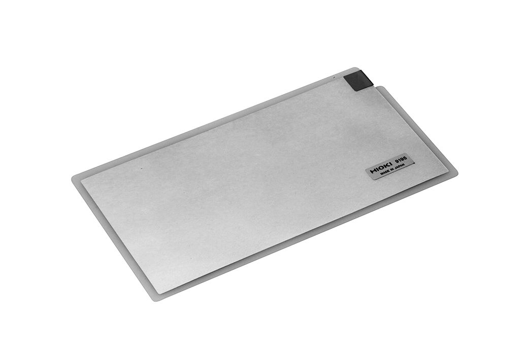
| Included accessories | Test lead L2200 (Red ×1, Black ×1) ×1 set, Enclosure probe 9195 ×1, Power cord ×3, Spare fuse for measurement line ×1, Instruction manual ×1 | |||||
ST5540, ST5541 List of functions (Network)
| Item | ST5540 | ST5541 | ||||
|---|---|---|---|---|---|---|
| Network A (Electrical Appliances and Materials Safety Act) |
○ | ○ | ||||
| Network B (Medical-use electrical devices) | ○ | - | ||||
| Network C (IEC 60990) | ○ | ○ | ||||
| Network D (UL) | ○ | ○ | ||||
| Network E (General-purpose 1) | ○ | ○ | ||||
| Network F (General-purpose 2) | ○ | ○ | ||||
| Network G (IEC 61010-1) | ○ | ○ | ||||
List of functions (Major functions)
| Item | ST5540 | ST5541 | ||||
|---|---|---|---|---|---|---|
| Power on polarity switching function | ○ | ○ | ||||
| Rated current 20 A | ○ | ○ | ||||
| Function for checking for blown fuses | ○ | ○ | ||||
| Frequency band switching | ○ | - | ||||
| 110% voltage output terminal (T3 terminal) | ○ | - | ||||
| S10, S12, S13, E terminal | ○ | - | ||||
List of functions (Testing leakage current mode)
| Item | ST5540 | ST5541 | ||||
|---|---|---|---|---|---|---|
| Earth leakage current | ○ | ○ | ||||
| Touch current | ○ | ○ | ||||
| Patient auxiliary current | ○ | - | ||||
| Patient leakage current | ○ | - | ||||
| Total patient leakage current | ○ | - | ||||
| Free current | ○ | ○ | ||||
| Enclosure - Earth leakage current | ○ | ○ | ||||
| Enclosure - Enclosure leakage current | ○ | ○ | ||||
| Enclosure - Line leakage current | ○ | ○ | ||||
| Patient leakage current I | ○ | - | ||||
| Patient leakage current II | ○ | - | ||||
| Patient leakage current III | ○ | - | ||||
Test probes (2)
*The L2200 and the 9195 are bundled
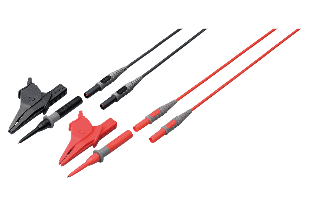
70 cm (2.30 ft.) length, detachable large alligator clips or needle tips are bundled, CAT IV 600 V, CAT III 1000 V
For the ST5540 series, 3156/3155
Printer options (2)
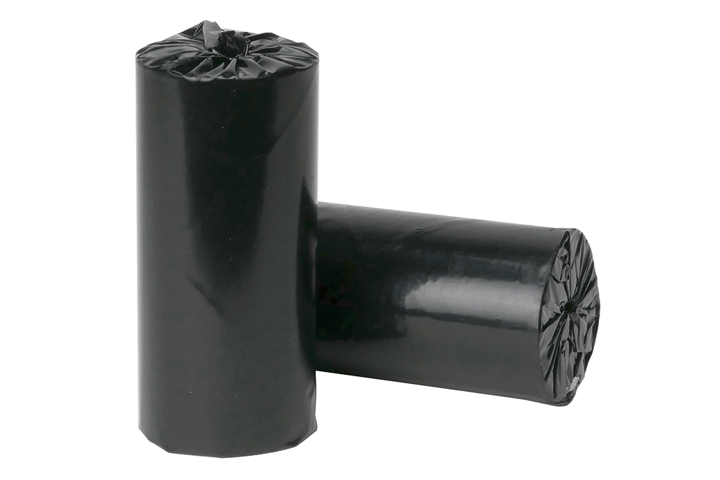
112 mm (4.41 in) × 25 m (82.03 ft), 10 rolls/set
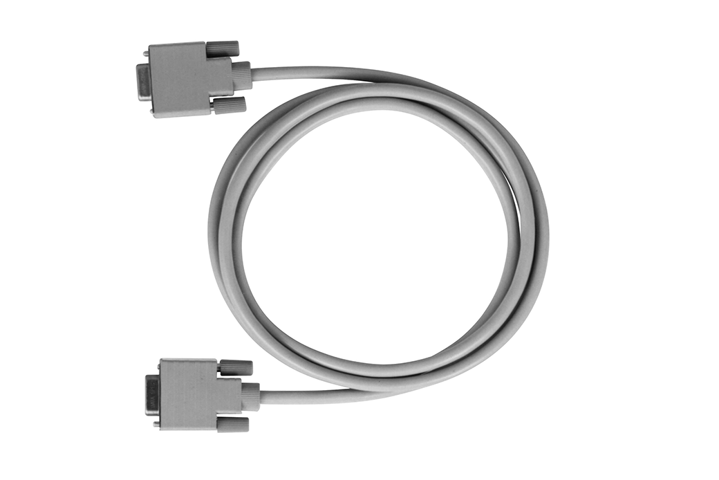
9 pin - 9 pin straight, 1.5 m (4.92 ft) length
PC communications (1)
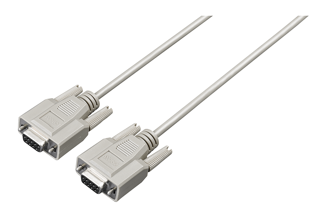
9 pin - 9 pin, cross, 1.8 m (5.91 ft) length
Other option (1)

Replacement fuse set (50 mA/250 V, 5 pieces)
Replacement Parts (6)
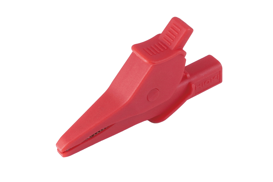
Order Code: Z7025
Replacement part for the red alligator clip of the product listed below:
L1000, L1000-05, L2200, L4935, L9197, L9257, L9438-50, L9438-53, L9787, L9844, P9000
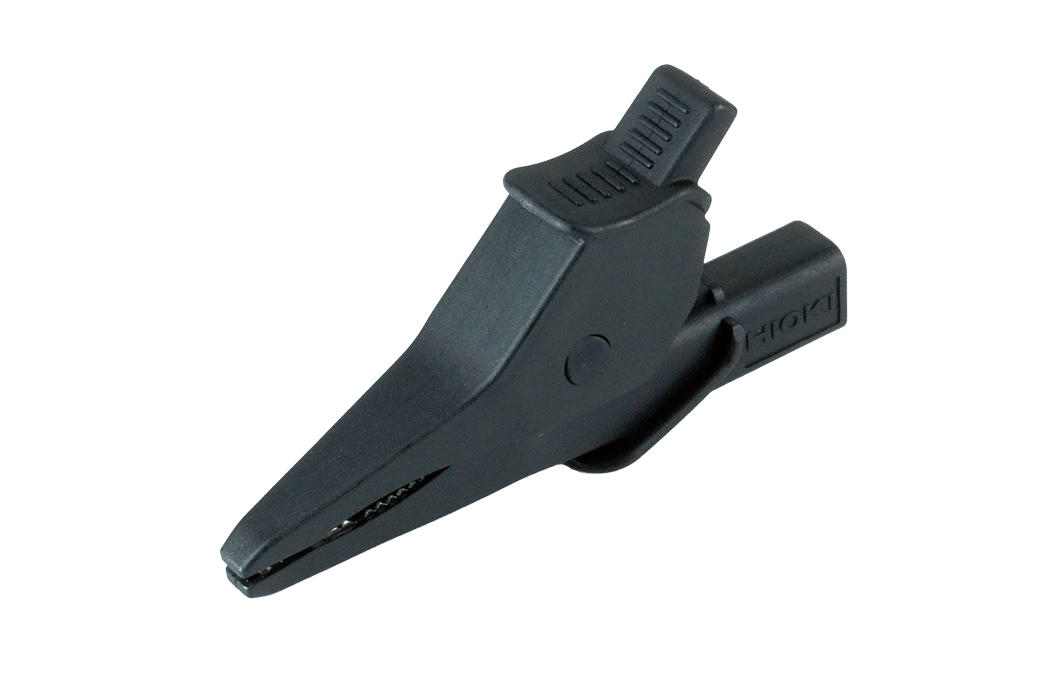
Order Code: Z7026
Replacement part for the black alligator clip of the product listed below:
L1000, L1000-05, L2200, L4935, L9197, L9257, L9438-50, L9438-53, L9787, L9788-11, L9844, P9000, SP7100, SP7150
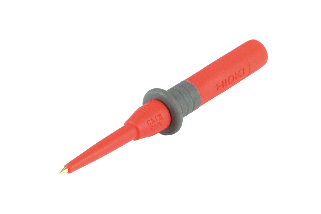
Order Code: Z7029
Replacement part for the red test pin of the product listed below:
L2200, L4938, L9787
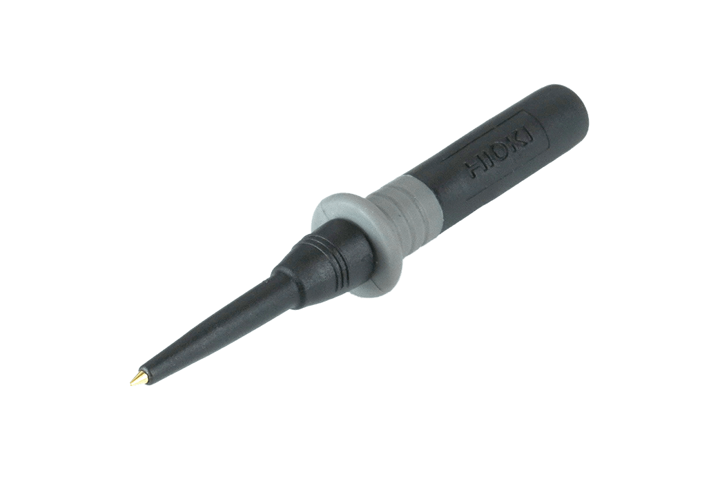
Order Code: Z7030
Replacement part for the black test pin of the product listed below:
L2200, L4938, L9787, L9788-11
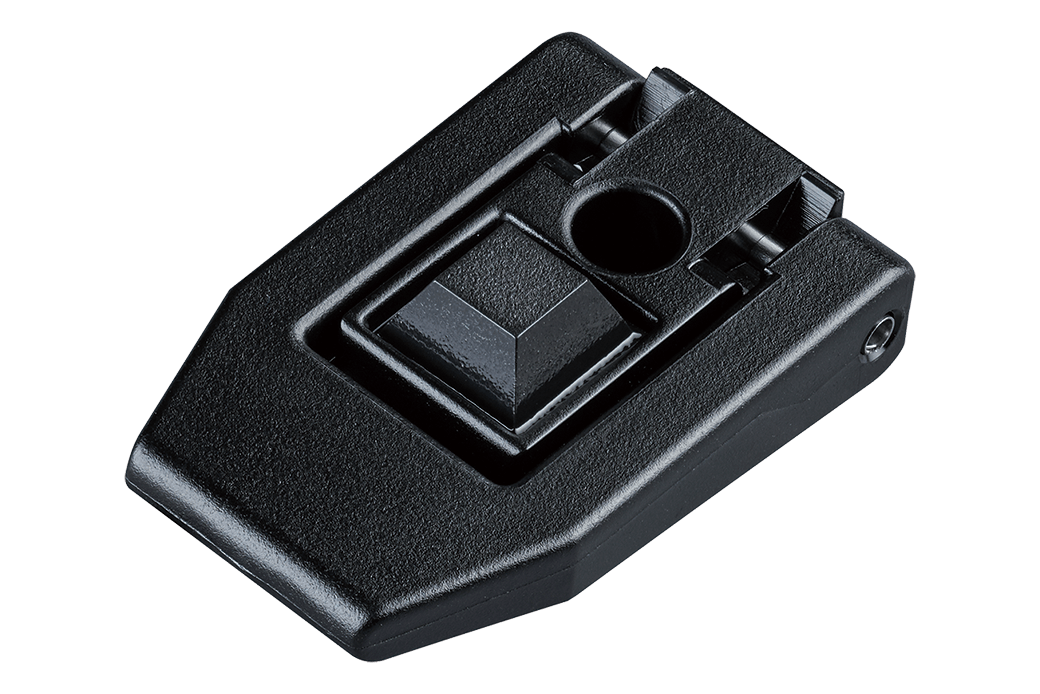
Order Code: Z7052
Single piece
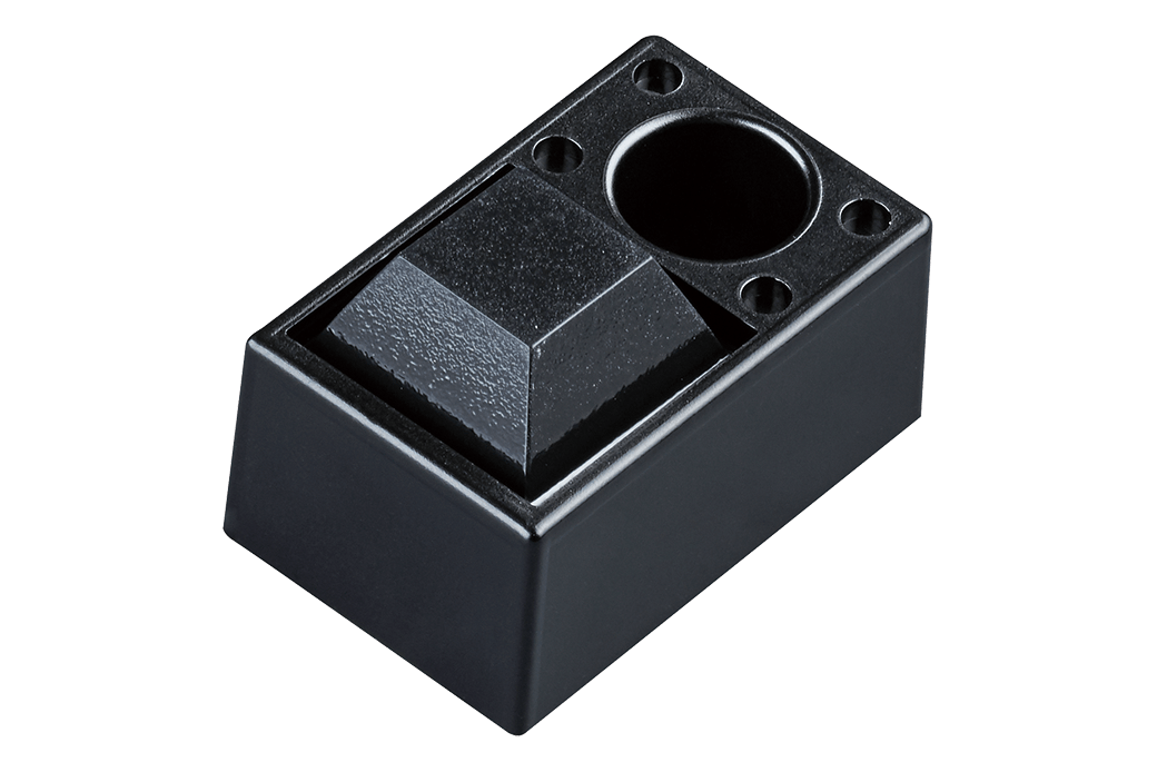
Order Code: Z7053
Single piece
-
LEAK CURRENT HiTESTER ST5541
 Test Report
Japanese
Test Report
Japanese
English Ver.01 -
LEAK CURRENT HiTESTER ST5540,ST5541
Instruction Manual
English
Ver.10
-
LEAK CURRENT HiTESTER ST5540,ST5541
Instruction Manual
Simplified Chinese
Ver.07
-
LEAK CURRENT HiTESTER ST5540,ST5541
Instruction Manual
Korean
Ver.02