How to Test Windings
How are windings tested?
Overview
Windings play an essential role in electronic circuits. Testing windings are necessary in a variety of situations. If an electronic device is operating properly, performing maintenance checks, and pinpointing where malfunctions or failures have occurred.
This page provides an easy-to-understand introduction to the principal methods used to test windings.
Inductance measurement
Inductance refers to the property by which changes in a current flowing through a winding or other circuit appear as induced electromotive force. You can picture it as resistance to the flow of an AC current. Windings that are designed to produce inductance are called inductors.
Some windings are coreless, meaning they use either air or a non-magnetic material for the core, while others have a core made of a magnetic material such as ferrite. Inductors with cores exhibit current dependence. LC resonance by the winding’s inductance and the core’s parasitic capacitance is known as self-resonance, and the frequency at which self-resonance occurs is known as the self-resonant frequency.
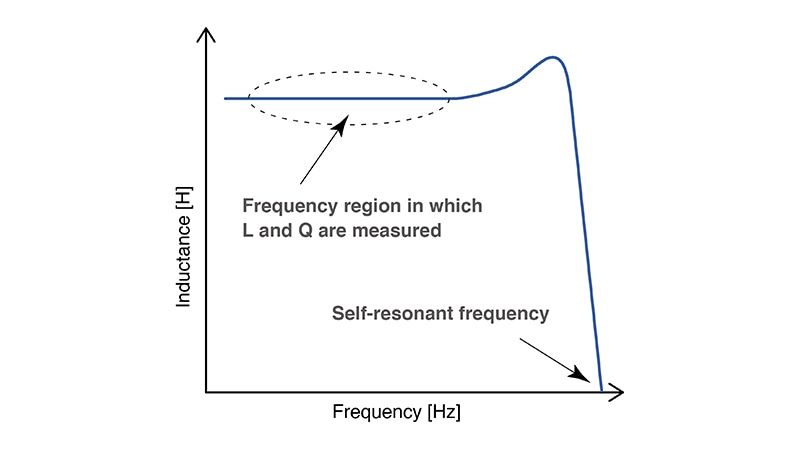 Frequency characteristics of the inductance
In winding evaluation using an LCR meter as part of inductance testing, L and Q measurements must be made at a frequency that is sufficiently lower than the self-resonant frequency.
When carrying out inductance testing, if you’re measuring an element with a low impedance of about 100 Ω or less, use the instrument’s series equivalent circuit mode. If you’re measuring an element with a high impedance of about 10 kΩ or greater, use the instrument’s parallel equivalent circuit mode.
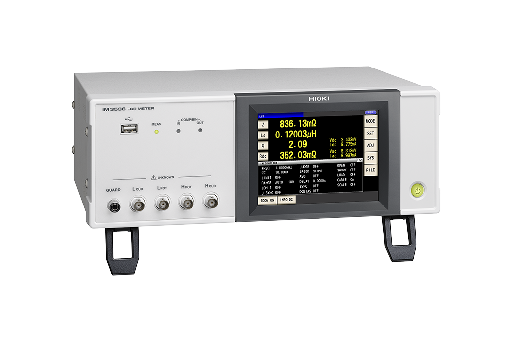
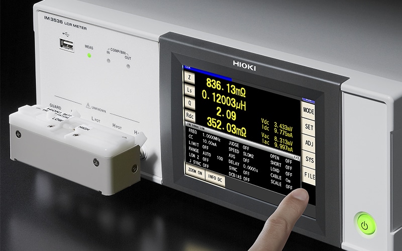 LCR Meter IM3536
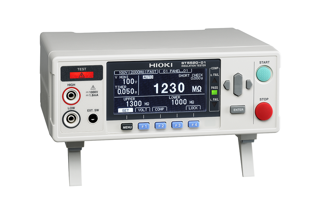
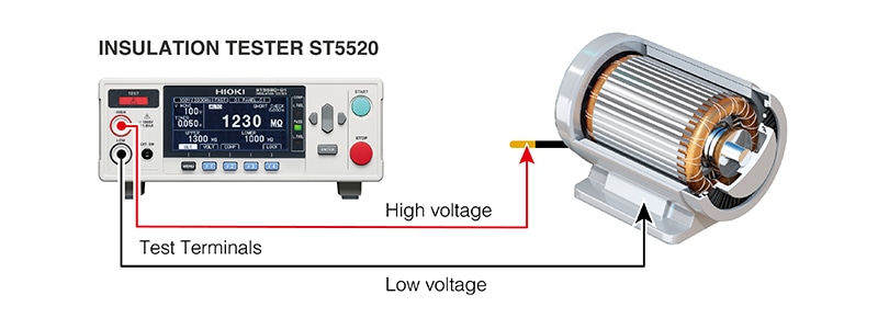
Insulation resistance measurement
Insulation resistance measurement is a type of testing that is designed to assess a winding’s insulation. The technique is often used in shipping inspections for products such as motor windings, maintenance testing, and testing to determine whether a winding is causing a malfunction or failure. Degradation of winding insulation poses an electric shock and short-circuit risk.
It’s necessary to investigate the condition of winding insulation in order to ensure product safety. During measurement, a winding resistance approaching infinity means you can conclude that the winding is properly insulated. However, a winding resistance reading such as 0 Ω means the winding’s insulation has been compromised, which could lead to problems.
It’s recommended to use an instrument with contact check functionality, which allows you to check for poor probe contact and broken wiring, so that you can avoid erroneously classifying a defective part as non-defective.
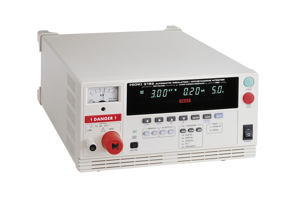
Withstand voltage testing
Like insulation resistance testing, withstand voltage testing provides a technique for investigating whether a winding has sufficient insulation to withstand its operating voltage.
At first glance, withstand voltage testing may appear to be the same thing as insulation resistance testing. The ultimate goal of both techniques is to keep products from causing electric shocks and fires, but they differ slightly in terms of their purpose.
Insulation resistance testing seeks to discover insulation defects by measuring resistance values. Withstand voltage testing is also designed to check whether an insulation breakdown has occurred. It’s typical in withstand voltage testing to use a test voltage that is determined by product-specific safety standards.
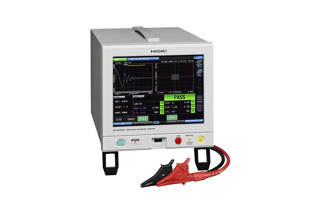
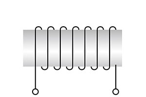
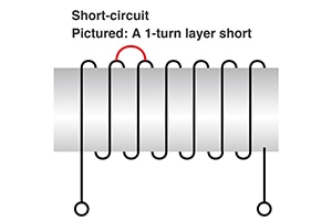
Impulse testing
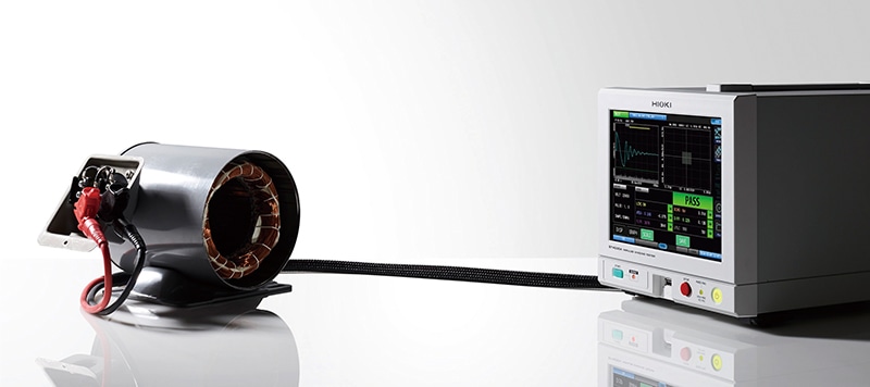
Impulse testing is a technique for detecting insulation failures in windings. The wire of windings must be insulated with a coating, but sometimes the insulation resistance is compromised, leading to a short-circuit. These shorts are known as layer shorts.
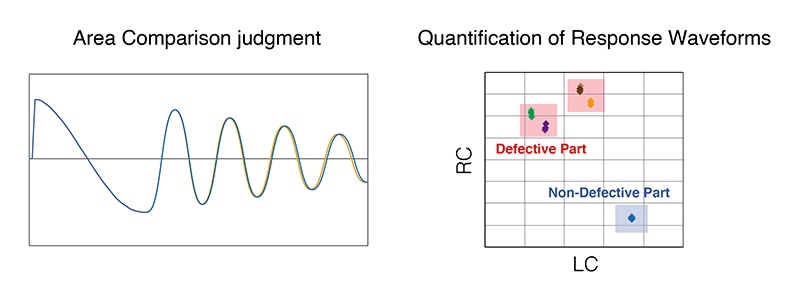
Generally, in impulse testing, the response waveform obtained by applying an impulse voltage to a known-good motor is used as the reference to determine whether the motor being tested is defective or non-defective by comparing the area of its response waveform to that of the reference waveform.
Changes in the response waveform are determined by the inductance value (L), winding resistance value (R), and capacitance value (C) that make up the motor.
Since winding shorts caused by insulation failures primarily show up as changes in the inductance component, it is possible to identify defective parts by the change in their waveforms.
Judgment based on area comparison, which is the typical method, quantifies the difference between response waveforms from non-defective and defective parts. Some instruments can quantify the response waveform itself.
Such values are calculated from the inductance value, winding resistance value, and capacitance value that make up the response waveform. (The technique uses a patent held by Toenec Corporation.)
There are various methods to test windings
It is necessary to test windings, which play an essential role in electronic circuits, when checking product quality and during maintenance and repair. There are various methods for testing windings. This article has introduced commonly used inductance measurement, insulation resistance measurement, withstand voltage testing, and impulse testing methods.
Please take advantage of what you’ve learned when testing windings.