DC Current Superposition Testing of Coils Using a Power Analyzer
DC Current Superposition Testing of Coils Using a Power Analyzer
We certified that a Power Analyzer can be used to perform high-accuracy DC current superposition testing (DC current bias testing) of high-current coils.
Issues in DC current bias testing
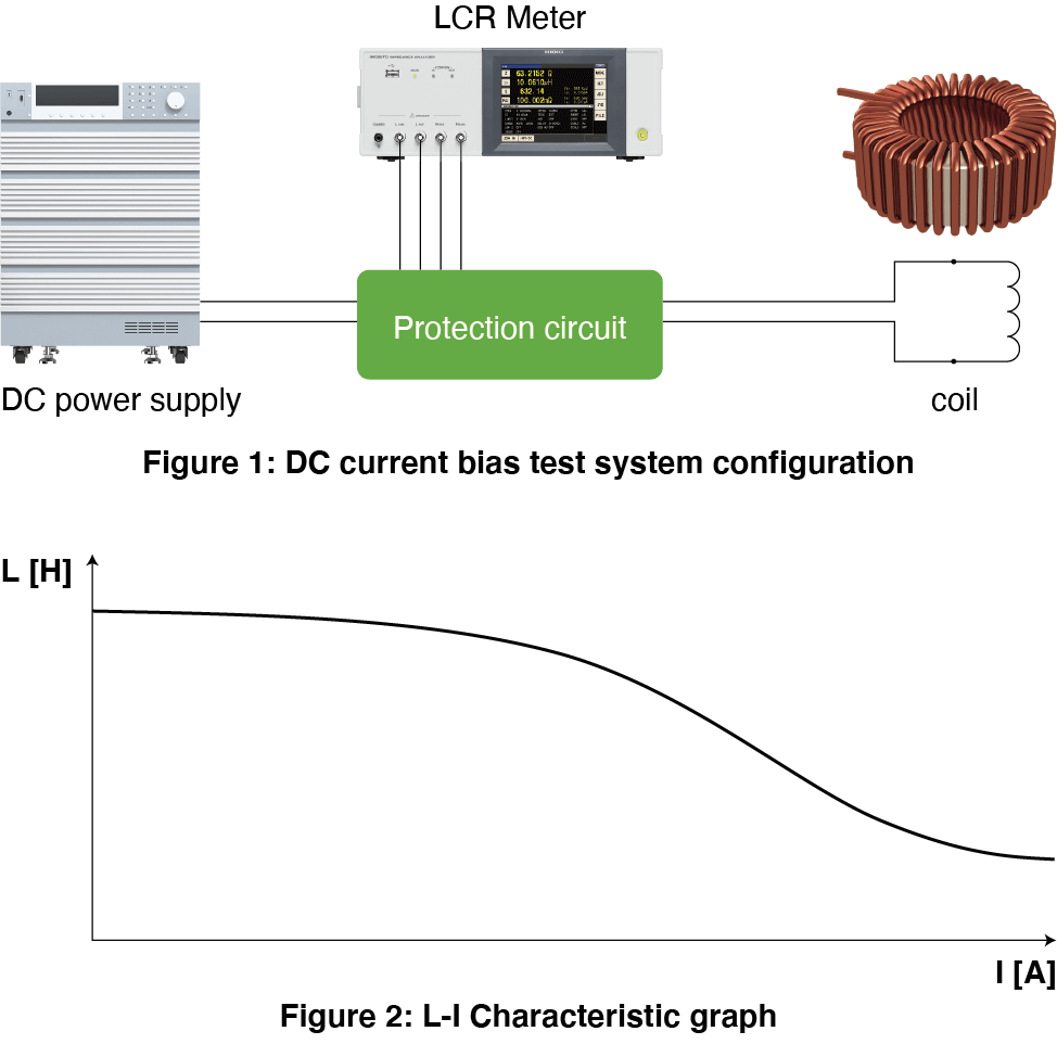
DC current superposition testing (DC current bias testing) of coils uses a DC source, LCR meter, and protective circuit (see Figure 1). Testing consists of recording inductance values with the LCR meter while sweeping through a range of current values with the DC source. An L-I characteristics graph is generated from the recorded data (see Figure 2). Protective circuits are either provided by instrument manufacturers based on characteristics such as the maximum current generated by the DC source and the measurement frequency or fabricated in response to a set of requirement specifications. Some manufacturers offer DC current superposition testing systems, but they support maximum currents ranging from 200 A to 300 A and cannot be used for testing at higher current values.
DC current superposition testing of coils suffers from the following issues:
• Limits on maximum current and frequency mean it may not be possible to use previously purchased or fabricated protective circuits.
• Commercially available DC current superposition testing systems max out at 200 A to 300 A and cannot be used to perform testing at higher current values.
Comparing values with data from a DC current bias tester
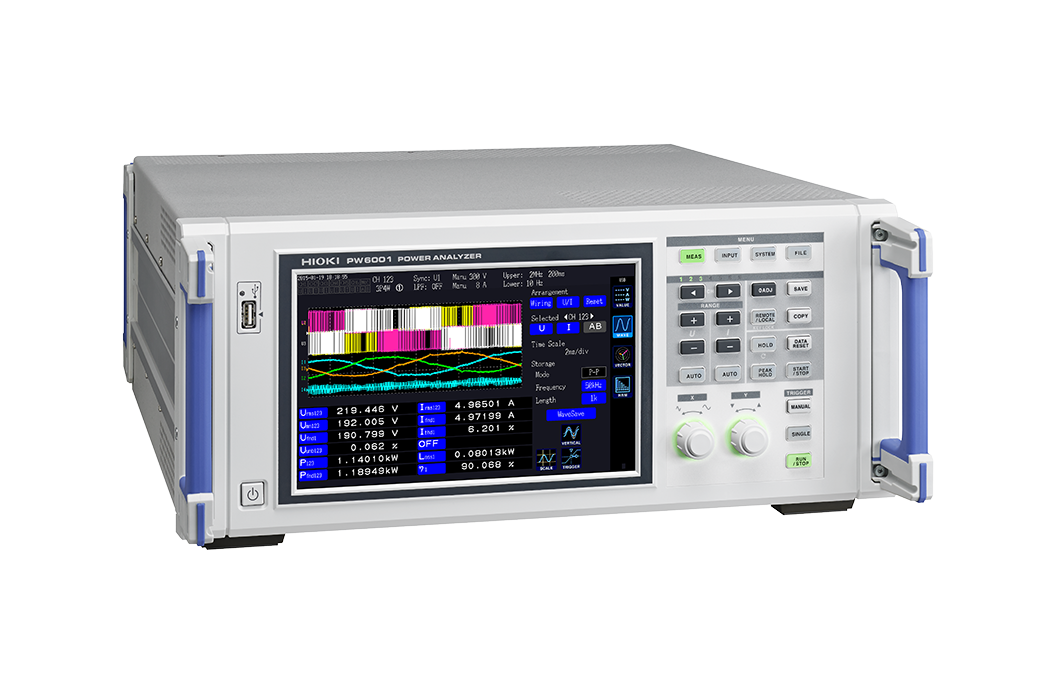
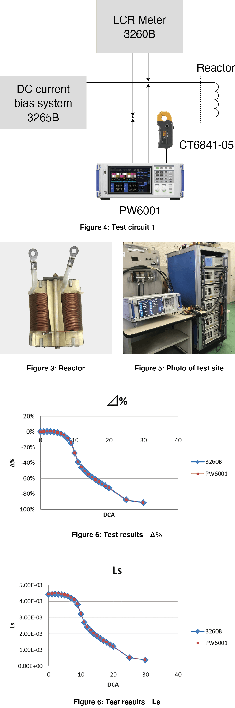
We prepared a 4 mH reactor (see Figure 3) and recorded inductance values from 0 A to 30 A with a measurement frequency of 1 kHz using a DC bias testing setup from Wayne Kerr. We also configured a Hioki Power Analyzer PW6001 internally with a formula to calculate inductance values from an LCR meter’s measurement AC voltage and AC current values as superposed on a bias device’s DC current and the measured phase angle value and used the instrument to measure inductance values (see Figures 4 and 5).
Sample and Equipment photos provided:
http://www.tokyo-seiden.co.jp/
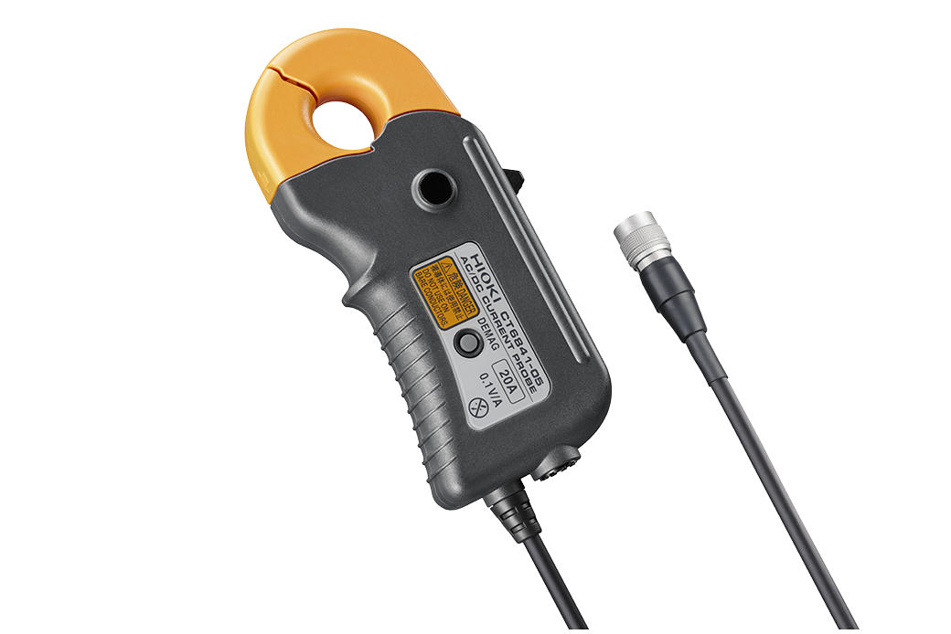
We set the measurement conditions of the 3260B to CV 1V and f=1kHz. The measurement current is 0.04A in calculation. As a result of measuring this small AC current using the current probe and PW6001, the inductance values of 3260B and PW6001 matched.
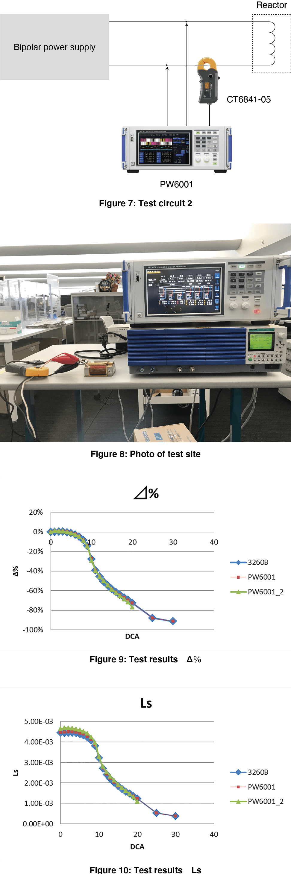
DC current bias testing using a Power Analyzer and bipolar power supply
Using a power supply that can output both DC and AC and PW6001, we will perform a DC current bias test. This time, we used KIKUSUI's bipolar power supply PBZ20-20 to superimpose DC current ranging from 1A to 20A and AC current of 0.2A, 1kHz as a signal for measurement, and calculated the inductance value with the calculation function of the power analyzer PW6001. (Figure 7) (Figure 8)
The label “PW6001_2” indicates data measured using the bipolar power supply and PW6001. The data aligns closely with the 3620B’s data.We were able to prove that the DC current bias test using the PW6001 power analyzer can replace the conventional test method using a DC power supply and LCR meter.