Evaluation of Efficiency in the Development of Multi-input MPPT Inverters
Introduction
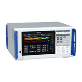
Monitoring and maximizing electricity output from solar (PV) systems is extremely important for users and stakeholders. Inverters that implement maximum power point tracking (MPPT) monitor solar panels (which produce varying amounts of energy) and control them to maximize output. This application note introduces the Power Analyzer PW8001 as being ideal for evaluating power conversion efficiency in the development of multi-input MPPT inverters (also known as string inverters) and describes the benefits of using the product’s optical link interface function.
What is a multi-input MPPT inverter?
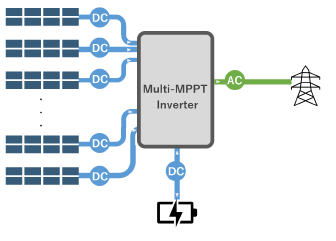
MPPT allows PV systems to operate while tracking which solar panel is outputting the highest level of power. This is especially useful for solar generation because power output varies continuously due to changes in weather conditions and other factors. The MPPT monitors and controls the system to ensure that the maximum possible amount of DC power is input to the inverter. By doing so, MPPT inverters can boost power generation efficiency. Furthermore, a multi-input MPPT inverter is an inverter with multiple MPPT circuits. This allows each solar string to generate power at the highest possible efficiency. A multi-input MPPT inverter provides great flexibility in terms of accommodating varying sunshine levels resulting from weather conditions and panel locations. They also excel in string expandability.
Measurement issues
To measure the total power conversion efficiency of a multi-input MPPT inverter, you must simultaneously measure multiple DC inputs and 3-phase AC outputs. In addition, it’s necessary to add another power measurement channel if the system is connected to a compound hybrid inverter that charges a storage battery system with surplus power. Furthermore, power and efficiency measurement are affected by issues such as the following:
- A typical power analyzer may not provide enough measurement channels to measure all the DC inputs and AC outputs.
- It’s time-consuming to use multiple power analyzers, synchronize and aggregate the data afterwards, and then perform calculations.
- Even if data is integrated prior to calculating efficiency, efficiency measurement results will exhibit variability.
Hioki measurement solution: 16-channel synchronized power measurement using an optical link interface function
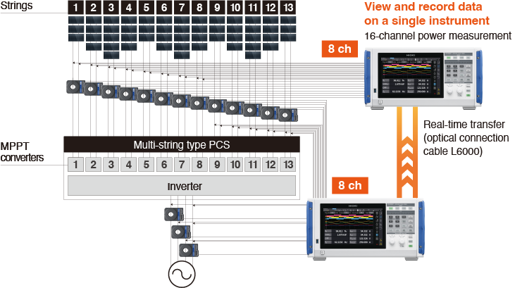
The Hioki Power Analyzer PW8001’s optical link interface function can be used to measure the power conversion efficiency of a multi-input MPPT inverter. By connecting two power analyzers with an optical connection cable, you can measure power across up to 16 channels as if the setup were a single instrument.
Example setup
Measure power conversion efficiency by using 13 channels to measure the inverter’s DC inputs and 3 channels to measure 3-phase AC output.
- PW8001-04: power analyzer with optical link interface option × 2
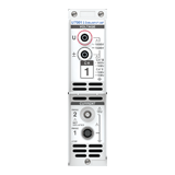
- U7001: 2.5 MS/s input module (with 1500 V DC input support) × 16
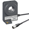
- CT6872: 50 A pass-through current sensor × 13
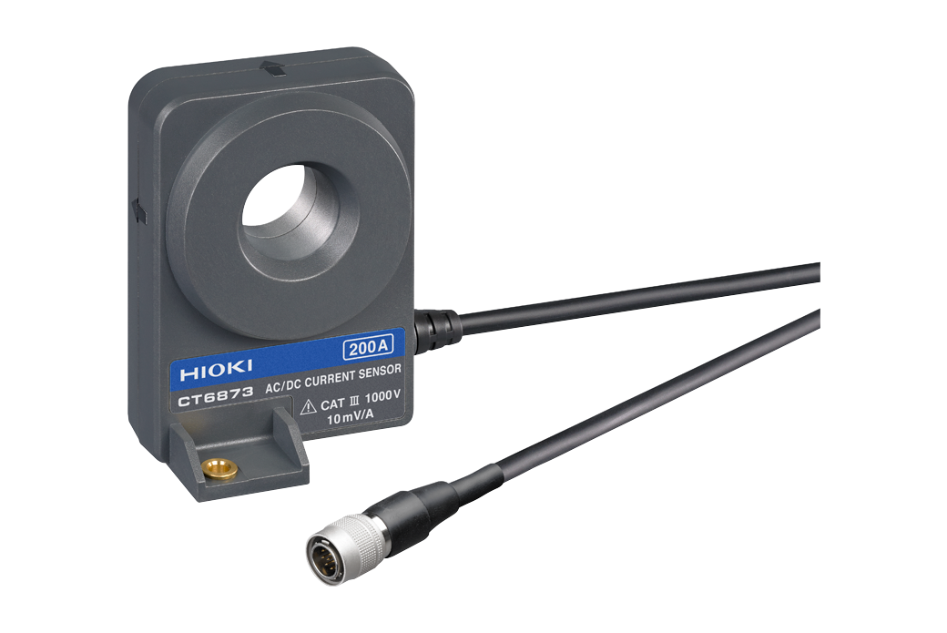
- CT6873: 200 A pass-through current sensor × 3
- L6000: optical connection cable × 1
Stable power measurement through optical link synchronization
The PW8001’s optical link interface function (factory-installed option) lets you synchronize two power analyzers and the timing at which their power calculation data are updated. One unit will be configured as primary and the other as secondary instruments. This approach yields stable power efficiency measurement results without any divergence in the two instruments’ data update timing.
Using one instrument for everything from configuration to data collection
By operating the primary instrument, you can configure both instruments’ settings and have the primary instrument collect data as the secondary instrument outputs data to it. As a result, you can collect data efficiently using a simple system setup, eliminating the need to operate the two instruments separately. Table 1 provides an overview of the optical link interface function.
Table 1: overview of the optical link interface function
| Function | Description |
|---|---|
| Equipment operation |
|
| Collectable data | Most parameters including the following can be collected by the primary unit: voltage, current, power, power factor, wideband harmonics (up to the 50th order). |
| Data calculations | Calculations are performed by the primary instrument using collected measurement data (efficiency and user-defined calculations) |
| Data output and storage |
|
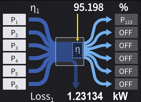
Fig. 1 shows a measurement screen for efficiency measurement of a 3-phase output inverter with 8 MPPT inputs using the PW8001’s optical link interface function.
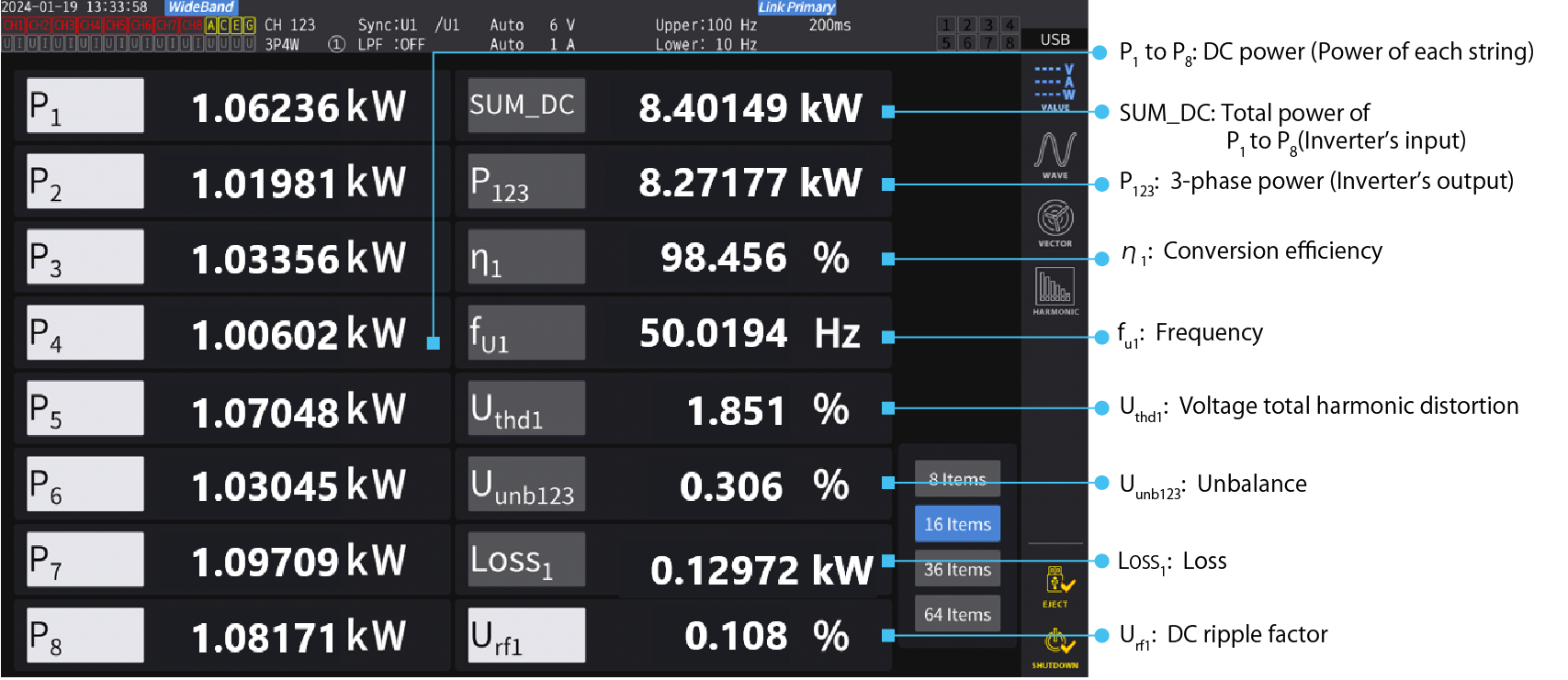 Fig. 1: Efficiency measurement of a 3-phase output inverter with 8 MPPT inputs using the PW8001’s optical link interface function
Conclusion
In order to accurately measure power conversion efficiency of multi-input MMPT inverters, it’s important to synchronize the timing at which data measured with power analyzers are updated. The Power Analyzer PW8001’s optical link interface function enables synchronized power measurement by two power analyzers. The function makes it possible to measure power conversion efficiency across many channels, a capability that’s useful for measuring power conversion efficiency in multi-input MPPT inverters.
For comprehensive details on the product, please explore the PW8001 product page. For inquiries such as quotes, demonstrations, and trial usage, please use Hioki’s contact form for a personalized reply from your closest or most appropriate Hioki representative. We are here to help tailor solutions to your needs.