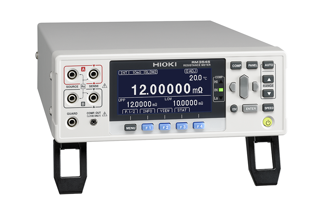
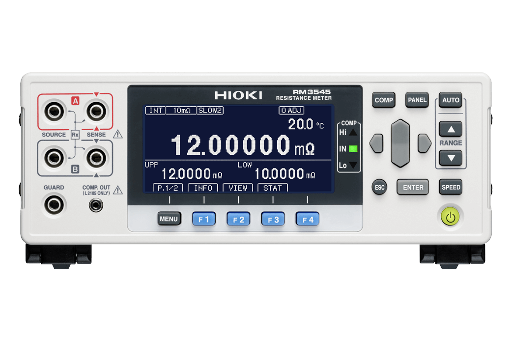
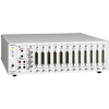
RESISTANCE METER RM3545
Featuring super-high accuracy and multi-channel capabilities
To Be Upgraded
The successor to RM3545 is RM3545A-1, and the successor to RM3545-02 (Support for the multiplexer unit) is RM3545A-2.
-

-
 RM3545-01
 -
-

-

-

Hioki DC resistance meters measure a broad range of resistance values at a high level of precision. The RM3545 is super-high-precision, multichannel-capable resistance meters that meet applications in advanced research and production for testing winding resistance of motors and transformers; contact resistance of power relays, switches, and connectors; and resistance of signal relays and magnetic parts.
Product Video
Key Features
- 0.006% basic accuracy, 0.01 μΩ max. resolution, 1A max. testing current
- Measure from 0.00 μΩ (testing current 1 A) to 1200 MΩ
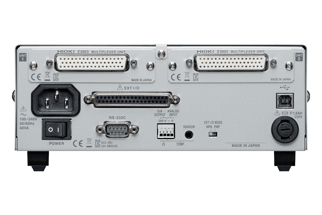
- Multiplexer Unit Z3003 (option) provides 20-channels of 4-terminal measurements for a complete assessment of multi-point signals (RM3545-02 only)
- Low-power resistance measurement with an open voltage not exceeding 20 mV
- High-speed, comprehensive productivity support delivers decisions in as little as 2.0 ms from start to finish
Model No. (Order Code)
| RM3545 | Discontinued |
|---|---|
| RM3545-01 | Built-in GP-IB interface |
| RM3545-02 | Discontinued, Support for the multiplexer unit |
How to Use Resistance Meters: Measuring Contact Resistance with the Low Power Resistance Function
IEC standards define the method by which to measure the contact resistance of connectors and relays used for very low signals. The Hioki RM3545 Resistance Meter meets those standards with its low power resistance function, also known as the dry circuit test. To reduce the effects on any deteriorating contact surface, the open terminal voltage is capped at 20mV, while the maximum measurement current never exceeds 1mA, delivering the ideal testing environment for measuring contact resistance from the 0.1μΩ to 1kΩ range.
How to Use Resistance Meters: Compensating for the Effect of Electromagnetic Force
When measuring low resistance, due to the voltage generated when different metals come into contact with one another (known as electromagnetic force, or EMF), the measurement values can be unstable. The Hioki RM3545 is built in with an Offset Voltage Compensation (OVC) function to correct for the effects of EMF, making the instrument ideal for measuring low resistance of the welding points of busbars.
Verify the Quality of the Battery by Seeing the Resistance of Battery Tab Welding and Busbars
Verify the quality of the battery by seeing the resistance of battery tab welding and busbars.
Discover energy loss to improve your batteries.
The RM3545 allows you to identify defective welding that causes increased resistance at junctions, causing greater heat/energy loss during charging and recharging.
*Watch with the video subtitles on, to see detailed descriptions.
Improve Productivity by Increasing the Number of Inspection Channels
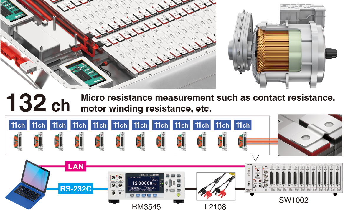
Combined with the SW1001/SW1002 switch mainframes, the number of measurement channels can be increased up to 132 channels, enabling scan measurements.
Basic specifications
| Resistance range | 10 mΩ (12.00000 mΩ display Max., 10 nΩ resolution) to 1000 MΩ range (1200.0 MΩ display Max., 100 kΩ resolution), 12 steps [LP ON] 1000 mΩ (1200.00 mΩ display Max., 10 µΩ resolution) to 1000 Ω range (1200.00 Ω display Max., 10 mΩ resolution), 4 steps Measurement accuracy: ±0.006 % rdg. ±0.001 % f.s. |
|---|---|
| Testing current | 1 A DC to 1 µA or less [LP ON] 1 mA to 5 μA DC |
| Open-terminal voltage | 20 V DC (10 kΩ range or more), 5.5 V DC max. (1000 Ω range or less) [LP ON] 20 mV DC max. |
| Temperature measurement | -10.0°C to 99.9°C, accuracy: ±0.50°C (Temperature Sensor Z2001 and RM3545 combined accuracy), -99.9°C to 999.9°C (analog input) |
| Measurement speed | Representative value: FAST (2.2 ms) / MED (50 Hz: 21 ms, 60 Hz: 18 ms) / SLOW1 (102 ms) / SLOW2 (202 ms) 10 mΩ range: FAST (41 ms) / MED (50 Hz: 61 ms, 60 Hz: 58 ms) / SLOW1 (141 ms) / SLOW2 (241 ms) |
| Functions | Temperature correction, temperature conversion, offset voltage compensation (OVC), comparator (ABS/ REF%), BIN, key-lock (OFF, menu lock, all lock), display digit count selection function (7- digit/ 6-digit/ 5-digit), automatic power supply frequency settings (AUTO/ 50Hz/ 60Hz), scaling, judgment sound setting, auto hold, averaging, statistical calculations, panel store/panel load, D/A output. |
| Multiplexer | [Only RM3545-02] Support Unit: Z3003 (Install up to 2 units) |
| Communication interfaces | Select from GP-IB (RM3545-01 only), RS-232C, Printer (RS-232C), or USB . Remote function, communications monitor function, data output function, memory (50) |
| Power supply | 100 V to 240 V AC, 50 Hz/60 Hz, Rated power consumption: 40 VA max. |
| Dimensions and mass | 215 mm (8.46 in) W × 80 mm (3.15 in) H × 306.5 mm (12.07 in) D [RM3545/RM3545-01] 2.5 kg (88.2 oz), [RM3545-02] 3.2 kg (112.9 oz) |
| Included accessories | Power cord ×1, Clip type lead L2101 ×1, temperature sensor Z2001 ×1, Male EXT I/O connector ×1, Instruction manual ×1, USB cable (A-to-B type) ×1, Spare fuse ×1 |
Measurement Leads / Input scanner (13)
The L2101, Z2001 are bundled with the RM3545 series
The L2100 is for low resistance measurement. Accuracy is guaranteed only for the following ranges with a measurement current is 100 mA or more.
10 mΩ range, 100 mΩ range (HIGH, LOW), 1000 mΩ range (HIGH only)
About lead length
A: From junction to probe, B: Probe length, L: Overall length
Note: For L2101 to L2104, length “A” can be extended by roughly 1.1 m (3.61 ft) by cutting the binding tube.
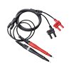
A: 300 mm (11.8 in.), B: 172 mm (6.8 in.), L: 1.4 m (4.6 ft.), 1000 V DC
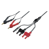
A: 250 mm (9.84 in), B:84 mm (3.31 in), L:1.5 m (4.92 ft), 60 V DC
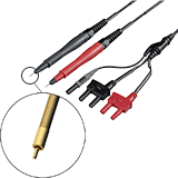
A: 250 mm (9.84 in), B:178 mm (7.01 in), L:1.5 m (4.92 ft), 60 V DC
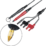
A: 250 mm (9.84 in), B:176 mm (6.93 in), L:1.5 m (4.92 ft), 60 V DC
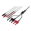
A: 280 mm (11.02 in), B:149 mm (5.87 in), L:1.5 m (4.92 ft), 60 V DC
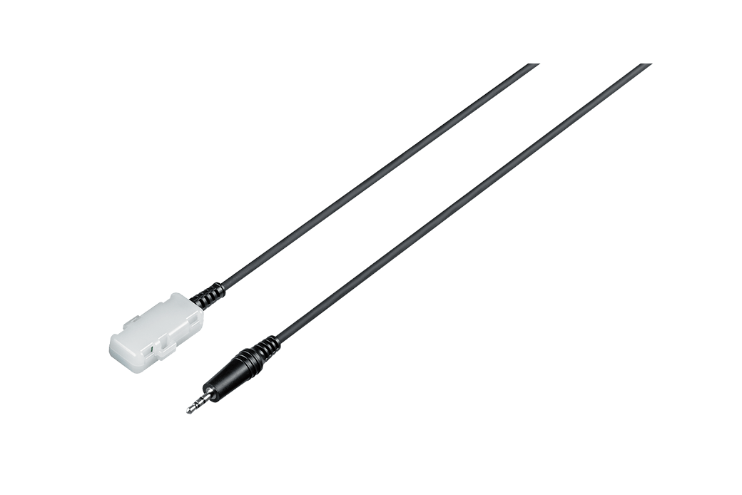
2 m (6.56 ft) length
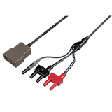
A:1215 mm (47.83 in), B:73.5 mm (2.89 in), L:1.5 m (4.92 ft)
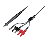
A:1120 mm (44.09in), B:84 mm (3.31 in), L:1.5 m (4.92 ft)
1.75 m (5.74 ft) length
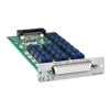
4-wire 10ch or 2-wire 21ch input scanning
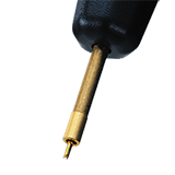
Replacement tip for pin type lead 9770,L2102
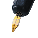
Replacement tip for pin type lead 9771,L2103
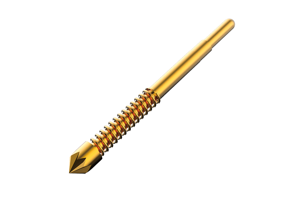
To replace the tip of models Pin Type Lead 9772, L2100, L2110, L2120, and Pin Type Probe L2003 (one pin)
PC Communication (2)
The 9151-02 is only for the RM3545-01
2 m (6.56 ft) length
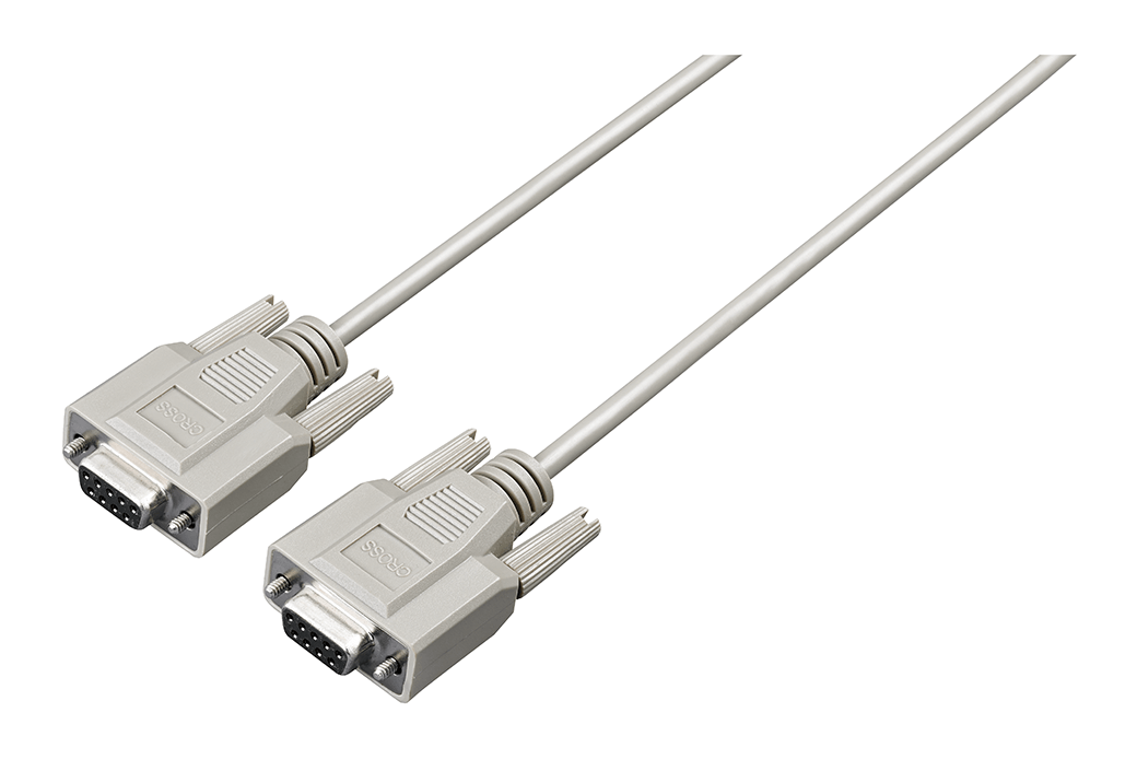
9 pin - 9 pin, cross, 1.8 m (5.91 ft) length
Compatible products (2)
Last update: Sept. 2021
Other option (1)

Replacement fuse set (1.6 A/250 V, 5 pieces)
- Measuring volume resistivity and surface resistivity of conductive materials using the four-point probe method
- Estimating the Length of Copper Wire
- Temperature Correction Using a Radiant Temperature Sensor for Measurement of the Resistance of Flat Enameled Wire
- AEC-Q200-compliant evaluation of the temperature of electronic components
- How to Directly Measure Volume Resistivity
-
Comprehensive Testing of Coils and Transformers


