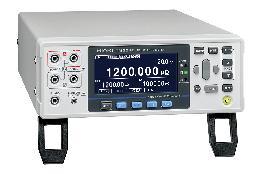
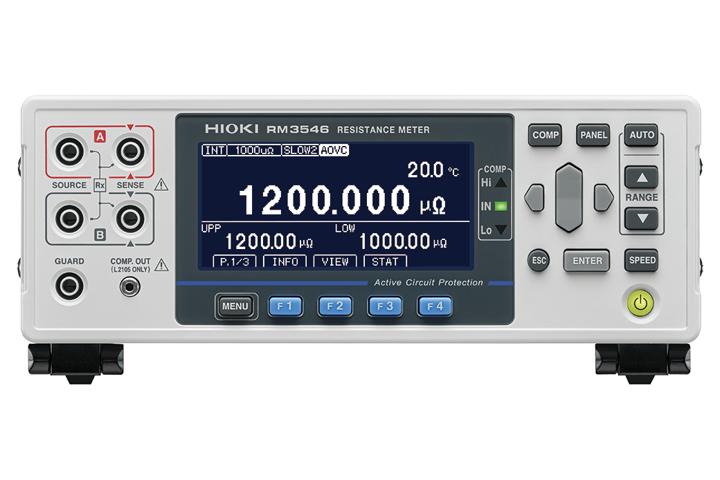
RESISTANCE METER RM3546
New Standard in Weld Resistance Inspection
NEW
In addition to the industry‘s highest level of resistance measurement accuracy, the Advanced Temperature Compensation (A-TC) function ensures that minute changes in resistance are quantified. Even in environments where temperatures change rapidly, such as immediately after welding, the system accurately detects slight differences in welding quality, contributing to the early detection of potential defective products. Furthermore, a new function has been added that instantly activates the protection circuit and shuts down the circuit when an over-input is detected. This reduces the risk of failure and prevents production line downtime. In addition, for production line system construction, support for "maximum allowable path resistance of 9Ω" and the provision of a dedicated probe kit support stable operation over the long term and seamless system construction.
Product Introduction Video
EVs (electric vehicles) and ESSs (energy storage systems) that support social infrastructure: The explosive growth of the battery market is creating unprecedentedly high-level demands such as design battery lifespans of over 20 years, ultra-fast charging, and high safety. To achieve the development and production of safer batteries, Hioki has developed the RM3546, which can perform high-precision inspections on welded areas where large currents flow.
Key Features
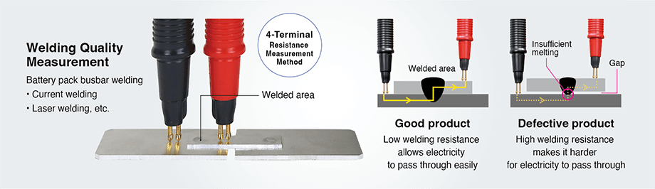
- Low-Resistance Measurement Optimized for Welding Quality Inspection in Battery Pack/Module Manufacturing Lines.
- Ultra-high precision measurement with 1 nΩ resolution to detect small changes in weld quality.
- Active Circuit Protection (up to DC 60 V) safeguards the measuring instrument from miswiring and incorrect contact.
- The A-TC function enables stable measurement even immediately after welding when temperatures are high, contributing to reduced takt time.
- The A-OVC function ensures measurement stability even in environments with large temperature variations.
- Increased Freedom in Cable Extension and Equipment Layout thanks to a maximum path resistance tolerance of 9Ω.*
*Conditions: PR1000 µΩ, 500 mA, SOURCE B–SOURCE A
Model No. (Order Code)
| RM3546 |
|---|
Measure low resistance values at high precision and high, 1 nΩ resolution
Current passes through the measurement target, such as the welded area, to measure electrical resistance. Good and defective products are sorted based on differences in resistance values. Weld resistance is as low as 10 µΩ to 100 µΩ. The RM3546 resistance meter is equipped with a 1000 µΩ range and can measure low resistance with high precision at 1 nΩ resolution. If the weld is insufficient, the resistance value becomes larger than in good products. By detecting slight differences in resistance between good and defective products, it determines pass/fail. All weld quality can be managed numerically on the production line, ensuring traceability.
Measures Low Resistance with High Precision Using Temperature Noise Compensation
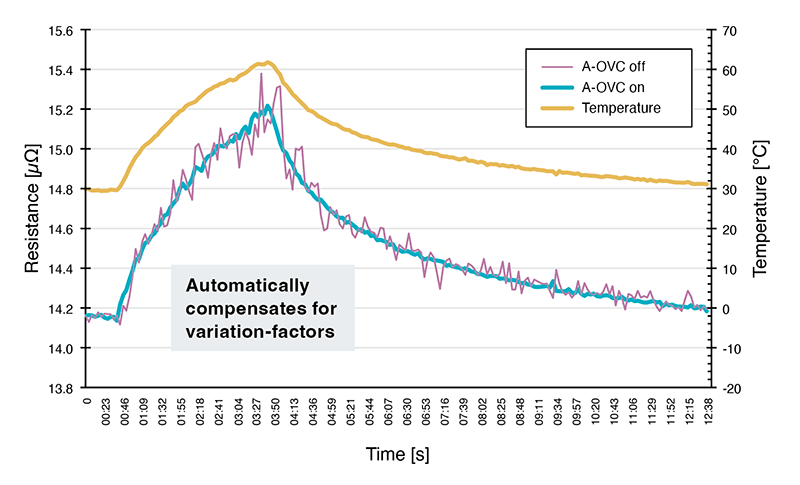
A-OVC function for stable measurement (Advanced Offset Voltage Compensation)
The RM3546 is equipped with an A-OVC function that automatically compensates for thermoelectric power, offset voltage inside the instrument, etc., to make measurement errors as close to zero as possible. It suppresses variations in measured values and enables measurements that maximize the performance of its 1 nΩ resolution.
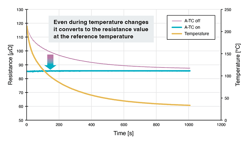
A-TC function compensates for temperature effects (Advanced Temperature Correction)
There is a correlation between resistance values and temperature. The RM3546 is equipped with the A-TC function that simultaneously measures the temperature and resistance value of the measurement target and compensates it in real time to the resistance value at a reference temperature. Even immediately after welding (when the temperature changes rapidly), it compensates to the resistance value at room temperature for accurate pass/fail judgement.
Evaluate Welding Quality with Resistance Measurement Values
By utilizing resistance measurement values, welding quality can be quickly assessed without waiting for the weld to cool. This method enables a reduction in takt time on production lines. For more details, please watch the demonstration video.
Simple Installation with Easy Wiring and Dedicated Probes
Design Systems Without Worrying About Path Resistance
The large tolerance for path resistance allows for design of installations without considering complicating factors such as cable resistance, contact probe resistance, object resistance, relay resistance, etc. High long-term measurement stability can be maintained even when path resistance increases due to cable extension or relay wear.
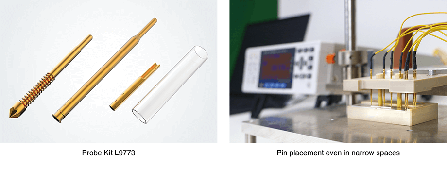
Customizable probes
A challenge during installation is obtaining appropriate probe pins and designing the probe section. The RM3546 offers a lineup of recommended probe pins so that measurement jigs can be freely designed according to the measurement target. This removes implementation barriers for users and significantly reduces man-hours.
Low-cost maintenance and channel expansion
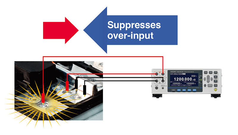
Prevent Sudden Malfunctions with the ACP Function (Active Circuit Protection)
The voltage protection circuit prevents malfunctions due to careless mistakes. Even if accidental contact is made with the battery's active terminal, the protection function automatically works to prevent damage. This not only reduces repair costs but also contributes to long-term stable operation of the line.
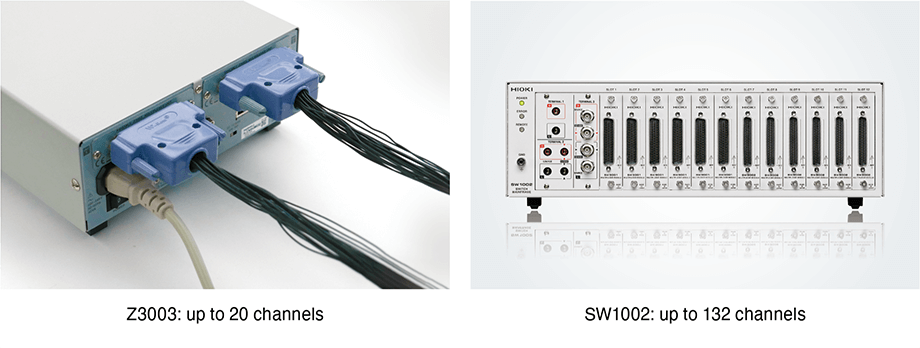
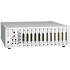
Up to 132 Channels per Unit
Up to 20 channels (4-terminal method) are supported by equipping 2 multiplexer units (Z3003). Finally, a total of 132 channels (4-terminal method) are possible when combining the switch mainframe SW1002. This meets the demand for multi-channel measurement with low cost and space savings.
Basic specifications
| Resistance range (13 ranges) | [Range, Maximum display value, Resolutions, Testing current (Measurement current) ] 1000 μΩ: 1200.000 μΩ, 1 nΩ, 1 A/500 mA 10 mΩ: 12.000 00 mΩ, 10 nΩ, 1 A/500 mA 100 mΩ: 120.000 0 mΩ, 100 nΩ, 1 A/100 mA 1000 mΩ: 1200.000 mΩ, 1 μΩ, 100 mA/10 mA 10 Ω: 12.000 00 Ω, 10 μΩ, 10 mA/1 mA 100 Ω: 120.000 0 Ω, 100 μΩ, 10 mA/1 mA 1000 Ω: 1200.000 Ω, 1 mΩ, 1 mA 10 kΩ: 12.000 00 kΩ, 10 mΩ, 1 mA 100 kΩ: 120.000 0 kΩ, 100 mΩ, 100 μA 1000 kΩ: 1200.000 kΩ, 1 Ω, 10 μA 10 MΩ 12.000 00 MΩ, 10 Ω, 1 μA 100 MΩ (100 MΩ range high-precision mode): 120.000 0 MΩ, 100 Ω, 100 nA 1000 MΩ: 1200.0 MΩ, 100 kΩ, 1 μA or less |
|---|---|
| Representative accuracy (High mode, A-OVC function enabled, SLOW2, no zero adjustment) | 1000 μΩ range: ±0.045% rdg ±0.010 % f.s. 10 mΩ range: ±0.045% rdg ±0.001 % f.s. 100 mΩ range: ±0.045% rdg ±0.001 % f.s. 1000 mΩ range: ±0.012% rdg ±0.001 % f.s. 1000 Ω range: ±0.006% rdg ±0.001 % f.s. |
| Testing current (Measurement current) | High mode: 1000μΩ (1 A) to 1000 MΩ (up to 1 μA) Low mode: 100 mΩ (100 mA) to 100 Ω (1 mA) |
| Measurement speed | Representative value: FAST (2.3 ms) / MED (50 Hz: 22 ms, 60 Hz: 19 ms) / SLOW1 (102 ms) / SLOW2 (202 ms) PR10 mΩ range*: FAST (21 ms) / MED (50 Hz: 41 ms, 60 Hz: 37 ms) / SLOW1 (121 ms) / SLOW2 (221 ms) |
| Path resistance tolerance (reference values) Path resistance between SOURCE B and SOURCE A (other than measurement target) |
Range of 100 mΩ or less (PR* mode off): max. 3.5 Ω Range of 100 mΩ or less (PR* mode on): max. 9.0 Ω |
| Maximum open-terminal voltage | Range: 1000 Ω or less: 8.0 V Range: 10 kΩ or greater: 20 V |
| Temperature measurement | Temperature Sensor (Z2001[included accessories]): -10.0˚C to 99.9˚C Analog input (Ex: Infrared thermometer): DC 0 V to 2.0 V |
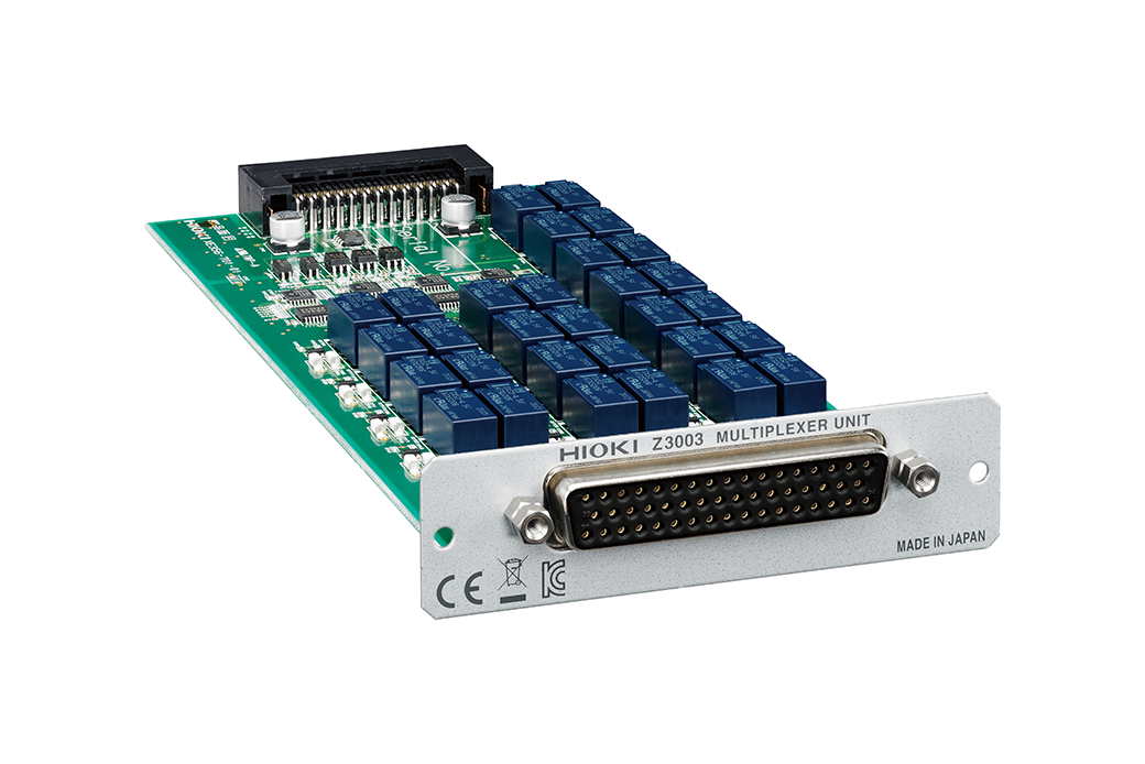
| Built-in Multiplexer (option) | Multiplexer unit Z3003 Number of installable units: Max. 2 Maximum number of channels: 20 channels (4-wire method), 42 channels (2-wire method) Switching time: 30 ms |
| External Multiplexer (option) | Switch Mainframe Maximum number of channels (SW1001): 33 channels (4-wire method) Maximum number of channels (SW1002): 132 channels (4-wire method) Switching time: 11 ms |
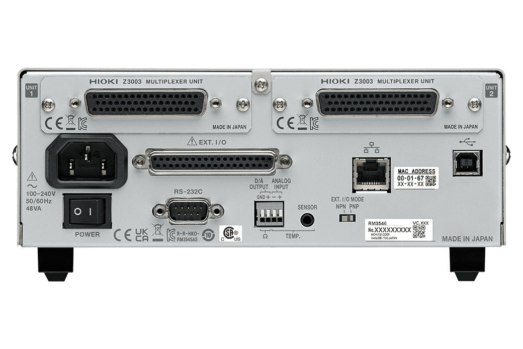
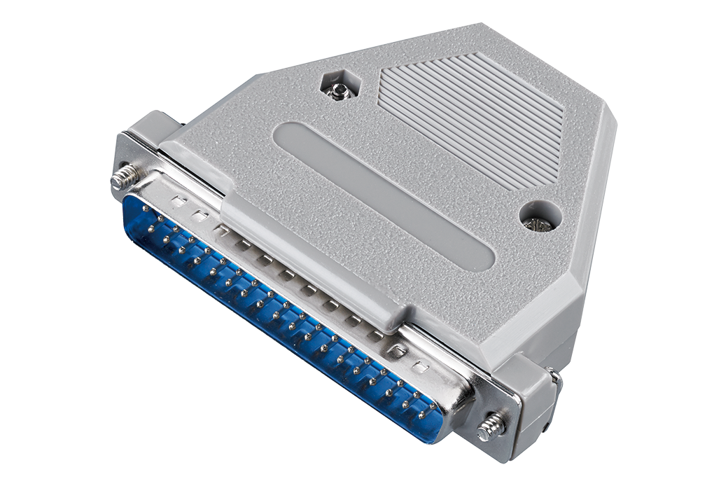
| Communication interfaces | LAN (TCP/IP, 10BASE-T/100BASE-TX), RS-232C (Max. 115200 bps, also used as printer interface), USB, EXT I/O (D-sub 37-pin, Analog output (D/A output voltage range: DC 0 V to 1.5 V) |
| Functions | Contact check, Zero adjustment (within each range ±50% f.s.) *1, Zero-adjustment-free accuracy guaranteed, OVC function, A-OVC function, Contact improvement function (max. applied voltage: 5V; max. applied current: 10 mA), Auto-hold function, Comparator, Temperature measurement function, Temperature correction (TC) function, Advanced Temperature Correction (A-TC) function, Temperature conversion (ΔT) function, Statistical calculation function, Delay function, Averaging function, Saving panels (saving of measurement conditions), Data memory function, Command monitor function (display of send/receive status of commands and queries),LabVIEW® Driver compatible*2 *1: Zero adjustment forcibly disabled for 100 MΩ or greater *2: LabVIEW Driver is the trademark or registered trademark of National Instruments. |
| Power supply | 100 V to 240 V AC, 50 Hz/60 Hz, Rated power consumption: 40 VA max. |
| Normal power consumption (Reference value) | 20 W |
| Dimensions and mass | 215 mm (8.46 in.) W × 80 mm (3.15 in.) H × 306.5 mm (12.07 in.) D (excluding protruding parts), 3.4 kg (119.9 oz.) |
| Included accessories | Power cord ×1, Temperature sensor Z2001 ×1, Male EXT I/O connector ×1, EXT. I/O connector cover ×1, Start up guide ×1, Operating Precautions ×1 |
*PR: Pure Resistance
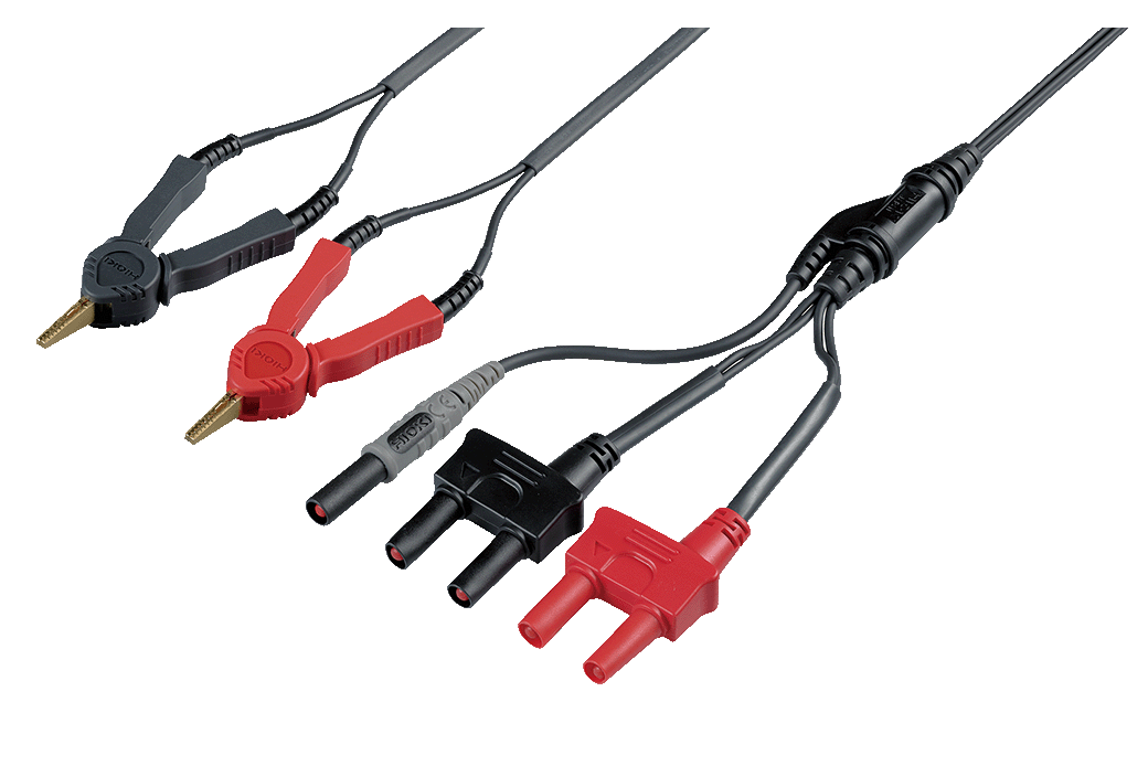
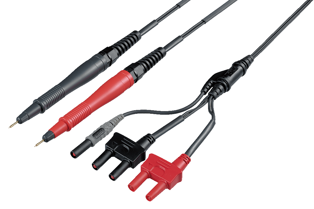
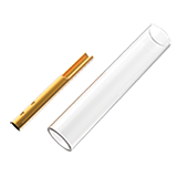
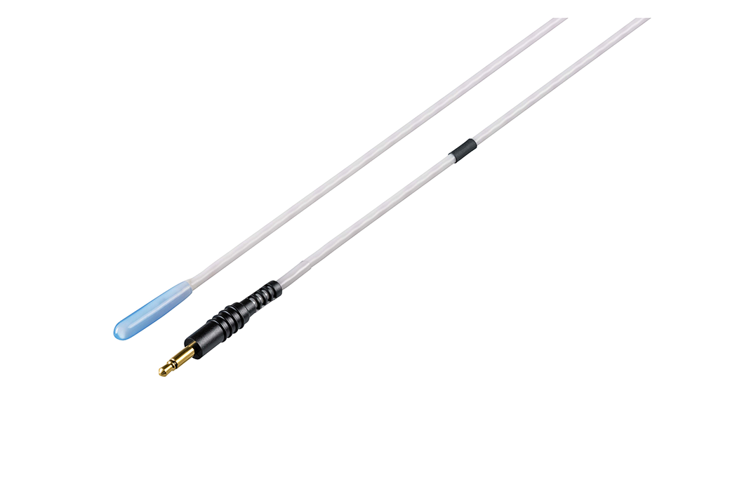
Measurement Leads (8)
The L2100 is for low resistance measurement. Accuracy is guaranteed only for the following ranges with a measurement current is 100 mA or more.
1000 μΩ range (HIGH, LOW), 10 mΩ range (HIGH, LOW), 100 mΩ range (HIGH, LOW), 1000 mΩ range (HIGH only)
About lead length
A: From junction to probe, B: Probe length, L: Overall length
Note: For L2101 to L2104, length “A” can be extended by roughly 1.1 m (3.61 ft) by cutting the binding tube.
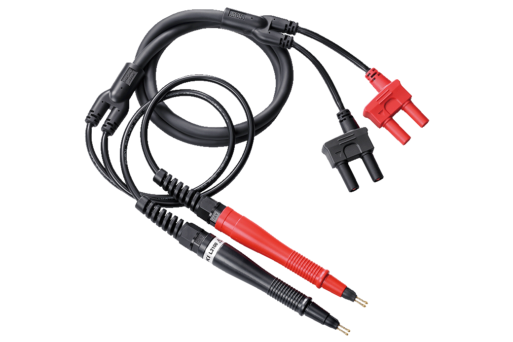
A: 300 mm (11.8 in.), B: 172 mm (6.8 in.), L: 1.4 m (4.6 ft.), 1000 V DC
A: 250 mm (9.84 in), B:84 mm (3.31 in), L:1.5 m (4.92 ft), 60 V DC
A: 250 mm (9.84 in), B:178 mm (7.01 in), L:1.5 m (4.92 ft), 60 V DC
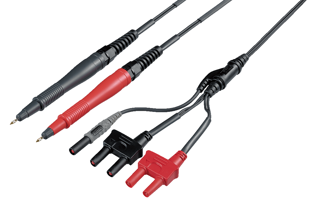
A: 250 mm (9.84 in), B:176 mm (6.93 in), L:1.5 m (4.92 ft), 60 V DC
L9773-01, L9773-02, L9773-03 set
10 pieces
10 pieces
10 pieces
PC Communication (3)
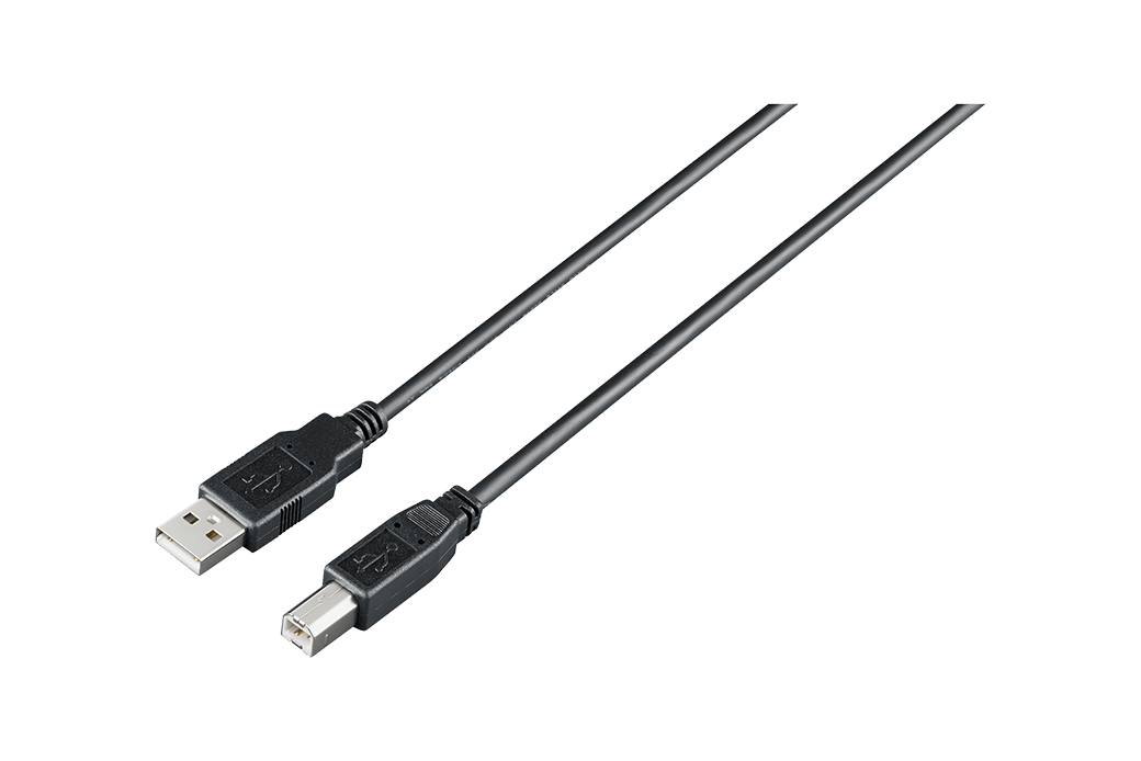
1 m
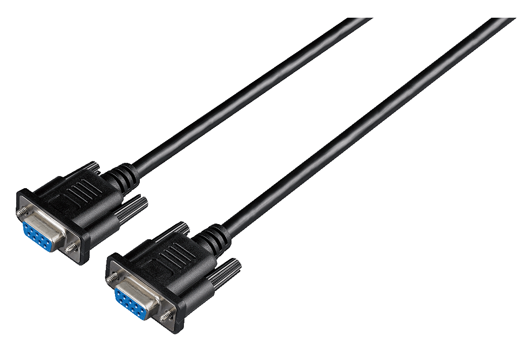
• For external control
• Double shielding
• 9-pin/9-pin, Cord length 3 m (9.8 ft.)
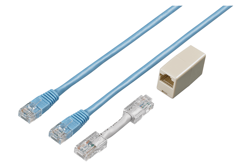
Straight Ethernet cable, supplied with straight-to-cross conversion adapter, 5 m (16.4 ft.)
Multichannel Options (3)
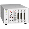
4-wire 10ch or 2-wire 21ch input scanning
Other Options (2)
Z2001 is included
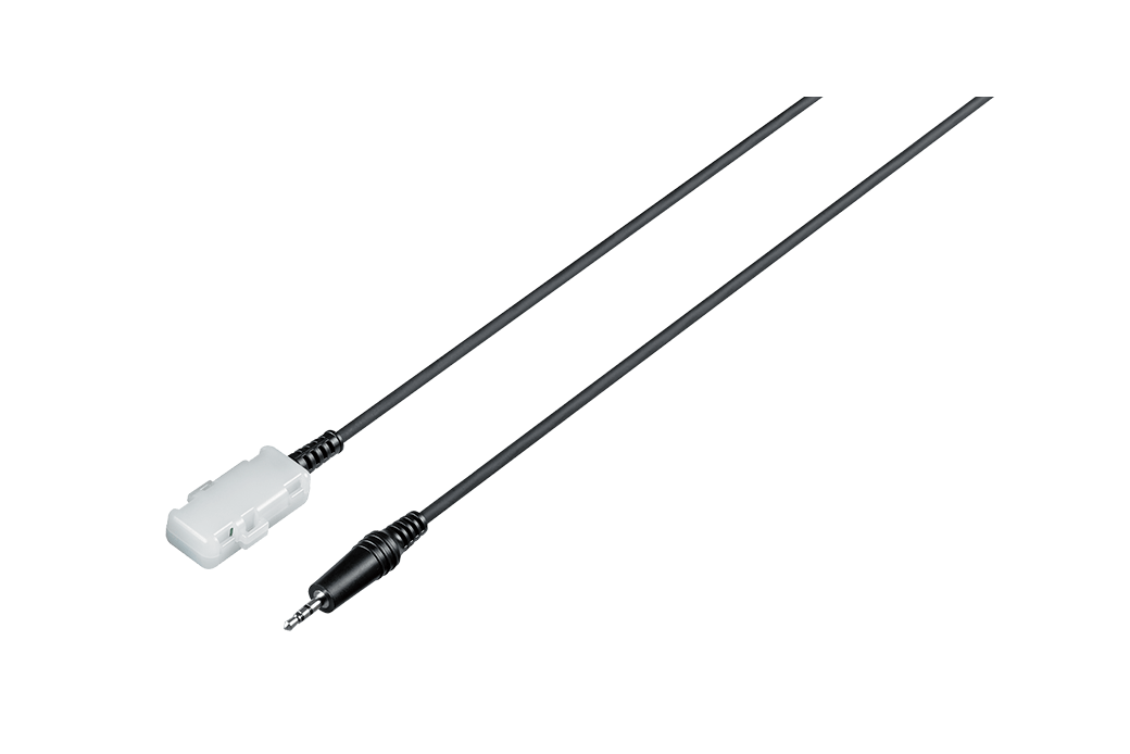
2 m (6.56 ft) length
1.75 m (5.74 ft) length
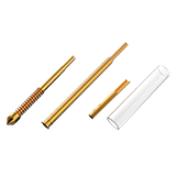
Replacement Parts (3)
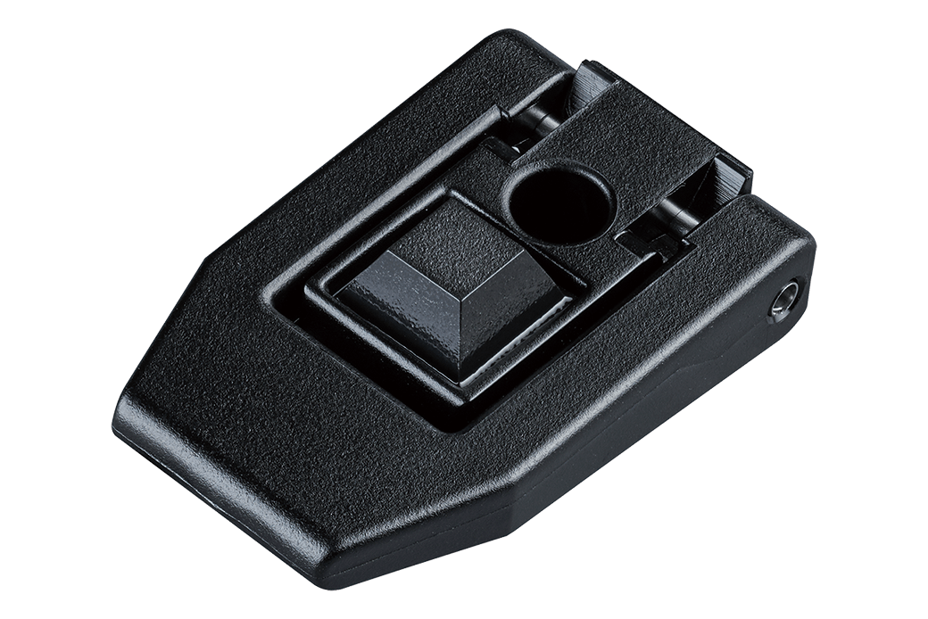
Order Code: Z7052
Single piece
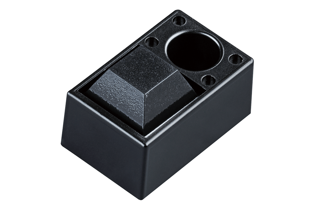
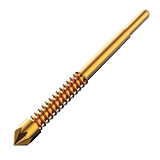
Order Code: Z7053
Single piece
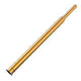
Order Code: Z7054
-
RESISTANCE METER RM3546
 Test Report
Japanese
Test Report
Japanese
English Ver.01 -
RESISTANCE METER RM3545A-1, RM3545A-2,RM3546
Instruction Manual
Spanish
Ver.01
-
RESISTANCE METER RM3545A-1, RM3545A-2, RM3546
Instruction Manual
Korean
Ver.01
-
RESISTANCE METER RM3545A-1, RM3545A-2, RM3546
Instruction Manual
Simplified Chinese
Ver.01
-
RESISTANCE METER RM3546, RM3545A-1, RM3545A-2
Startup Guide
Korean
Ver.02
-
RESISTANCE METER RM3546, RM3545A-1, RM3545A-2
Startup Guide
Simplified Chinese
Ver.02
-
RESISTANCE METER RM3545A-1, RM3545A-2,RM3546
Instruction Manual
English
Ver.01
-
RESISTANCE METER RM3545A-1, RM3545A-2,RM3546
Startup Guide
English
Ver.01
-
RESISTANCE METER RM3544-01,RM3545,RM3545-01,RM3545-02,RM3545A-1,RM3545A-2,RM3546
Communication Command Instruction Manual
English
Ver.05
-
RESISTANCE METER RM3546
Ver.00