Using and function of digital multimeters
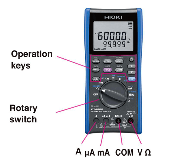
Digital multimeter (DMM) part names
The rotary switch is used to switch among measurement parameters (AC voltage, DC voltage, continuity check, resistance, capacitance, current, etc.) depending on the application in which the digital multimeter is being used.
The terminals into which the test leads (measurement cables) are inserted vary depending on the parameter being measured. For all parameters other than current, the red test lead is connected to the “VΩ” terminal, and the black test lead is connected to the “COM” terminal.
The operation keys are used to measure DC and AC voltage and current, to access other measurement parameters such as temperature and diode check functionality, and to utilize other functionality such as holding measured values.
*This description uses the DT4282 for explanatory purposes. Please check the product specifications for other models as specifications and settings vary.
Using digital multimeters (DMMs): Measuring AC voltage
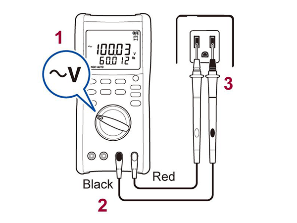
To measure an AC voltage, for example an outlet or circuit breaker’s line voltage or a piece of equipment’s supply voltage, set up the digital multimeter as follows:
1. Rotary switch position: ~V (“1” in figure)
2. Test lead connections to digital multimeter: Black (negative) to COM and red (positive) to VΩ (“2” in figure)
3. Test lead connections to outlet: “3” in figure
(When performing AC RMS measurement, there is no need to concern yourself with polarity.)
Caution: Do not connect either test lead to the “A” terminal. Some models have a shutter function designed to prevent the inadvertent connection of a test lead to the “A” terminal, while other models lack an “A” terminal entirely. Hioki digital multimeters also have an internal fuse designed to protect against the possibility of a test lead being inadvertently connected to the “A” terminal. For more information, please check the product specifications for each product. Verify that the voltage of the circuit being measured falls within the digital multimeter’s input specifications.
*This description uses the DT4282 for explanatory purposes. Please check the product specifications for other models as specifications and settings vary.
Using digital multimeters (DMMs): Measuring DC voltage
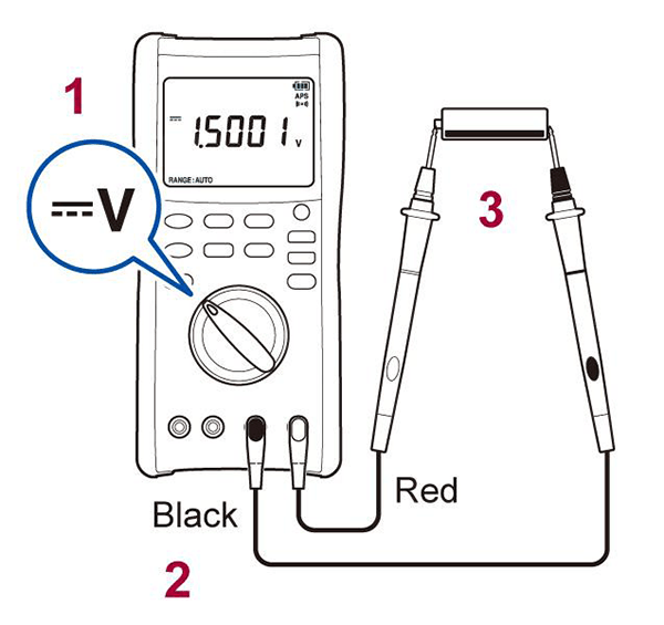
To measure a DC voltage, for example the output voltage of a solar panel, an instrumentation board’s 24 V DC signal, or a battery’s voltage, set up the digital multimeter as follows:
1. Rotary switch position: :::V (“1” in figure)
2. Test lead connections to digital multimeter: Black (negative) to COM and red (positive) to VΩ (“2” in figure)
3. Test lead connections to DC voltage source: Black to negative side and red to positive side (“3” in figure)
Caution: Do not connect either test lead to the “A” terminal. Some models have a shutter function designed to prevent the inadvertent connection of a test lead to the “A” terminal, while other models lack an “A” terminal entirely. Hioki digital multimeters also have an internal fuse designed to protect against the possibility of a test lead being inadvertently connected to the “A” terminal. For more information, please check the product specifications for each product. Verify that the voltage of the circuit being measured falls within the digital multimeter’s input specifications.
*This description uses the DT4282 for explanatory purposes. Please check the product specifications for other models as specifications and settings vary.
Using digital multimeters (DMMs): Checking continuity
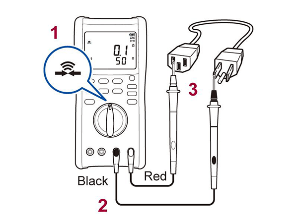
To investigate a wire break or check a wire harness cable, set up the digital multimeter as follows:
1. Rotary switch position: (“1” in figure)
2. Test lead connections to digital multimeter: Black (negative) to COM to red (positive) to VΩ (“2” in figure)
3. Test lead connections to object under measurement: “3” in figure (no polarity)
If continuity is detected, the digital multimeter will indicate that fact on its display and beep. If continuity is not detected, for example due to a wiring break, no value will be indicated, and no beep will sound.
Caution: Shut off the supply of power to the circuit being measured before measurement.
*This description uses the DT4282 for explanatory purposes. Please check the product specifications for other models as specifications and settings vary.
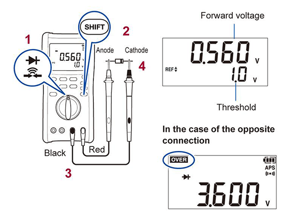
Using digital multimeters (DMMs): Checking a diode
To diagnose a diode failure, set up the digital multimeter as follows:
1. Rotary switch position: “1” in figure
2. Control key operation: “2” in figure
3. Test lead connections to digital multimeter: Black (negative) to COM and red (positive) to VΩ (“3” in figure)
4. Test lead connections to diode under measurement: Black to cathode side (side with the bar mark) and red to anode side (side without the bar mark) (“4” in figure)
The digital multimeter will show the diode’s forward voltage if connected in the forward direction and “OVER” if connected in the reverse direction.
Caution: Shut off the supply of power to the circuit being measured before measurement.
*This description uses the DT4282 for explanatory purposes. Please check the product specifications for other models as specifications and settings vary.
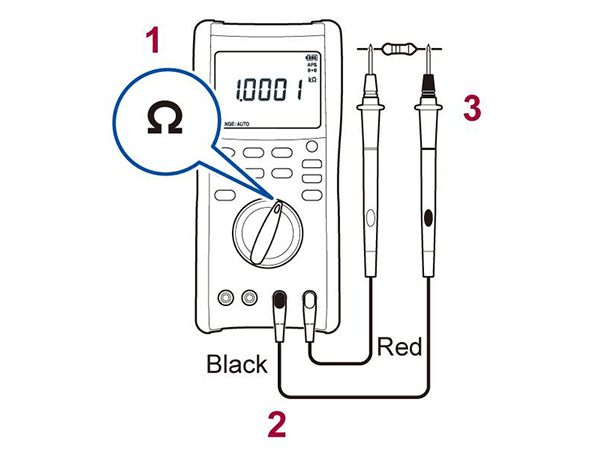
Using digital multimeters (DMMs): Resistance measurement
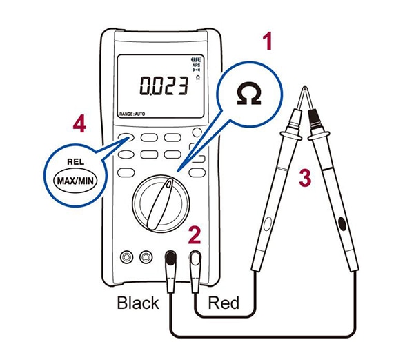
To measure resistance, set up the digital multimeter as follows:
1. Rotary switch position: “1” in figure
2. Test lead connections to digital multimeter: Black (negative) to COM and red (positive) to VΩ (“2” in figure)
3. Test lead connections to resistor: “3” in figure (no polarity)
Caution: Shut off the supply of power to the circuit being measured before measurement.
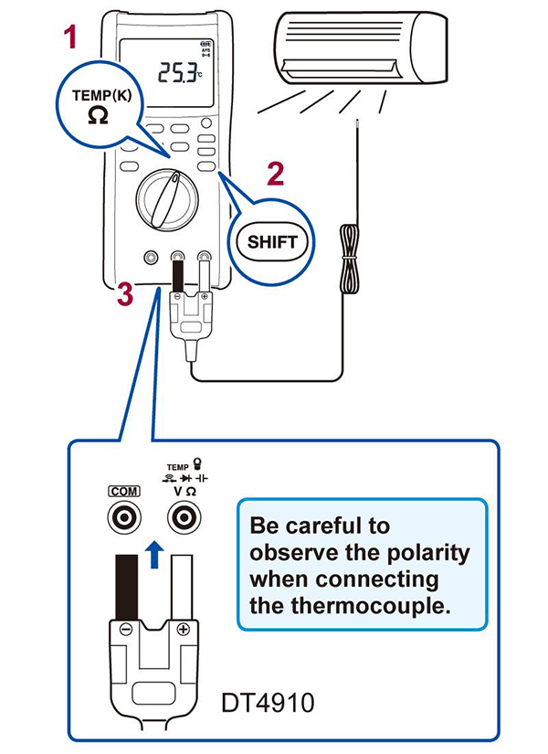
Using digital multimeters (DMMs): Measuring temperature
To measure temperature, for example the discharge temperature of an air conditioner, set up the digital multimeter as follows:
1. Rotary switch position: “1” in figure
2. Control key operation: “2” in figure
3. Test lead connections to digital multimeter: Using DT4910 Thermocouples (K) (option) (“3” in figure)
*Other K thermocouple sensors may also be used.
*This description uses the DT4282 for explanatory purposes. Please check the product specifications for other models as specifications and settings vary.
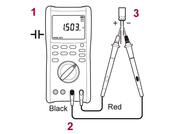
Using the digital multimeter (DMM): Measuring capacitance
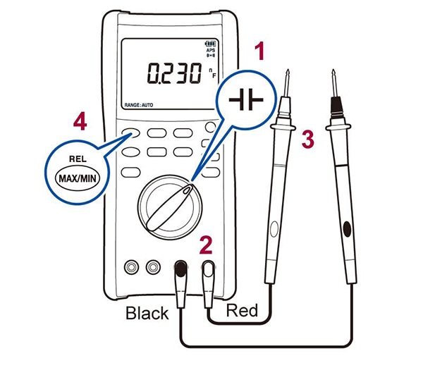
To measure a capacitor, set up the digital multimeter as follows:
1. Rotary switch position: “1” in figure
2. Test lead connections to digital multimeter: Black (negative) to COM and red (positive) to VΩ (“2” in figure)
3. Test lead connections to capacitor: For a polar capacitor, red lead to positive terminal and black lead to negative terminal (“3” in figure)
Capacitor capacitance display: F, μF, nF, pF
*This description uses the DT4282 for explanatory purposes. Please check the product specifications for other models as specifications and settings vary.
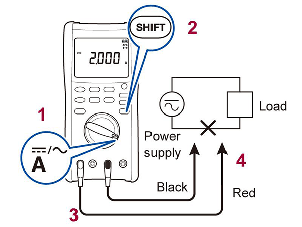
Using the digital multimeter (DMM): Measuring DC current
To measure current in a DC circuit, set up the digital multimeter as described below. The digital multimeter should be connected in series between the load side and the power supply side of the circuit by cutting the wire indicated with an “X” in the figure.
1. Rotary switch position: “1” in figure
2. Control key operation: “2” in figure
3. Test lead connections to digital multimeter: Black (negative) to COM and red (positive) to A (“3” in figure)
4. Test lead connections to circuit: Black to negative side of power supply and red to load side (so that the digital multimeter is in series with the power supply and load) (“4” in figure)
Caution: Shut off the supply of power to the circuit being measured before measurement and then turn it back on after connecting the digital multimeter. Exercise care not to apply a voltage (i.e., not to connect the digital multimeter in parallel with the power supply). Check the maximum current value that the digital multimeter can measure and only use it to measure circuits with currents that are less than or equal to that value.
*This description uses the DT4282 for explanatory purposes. Please check the product specifications for other models as specifications and settings vary.
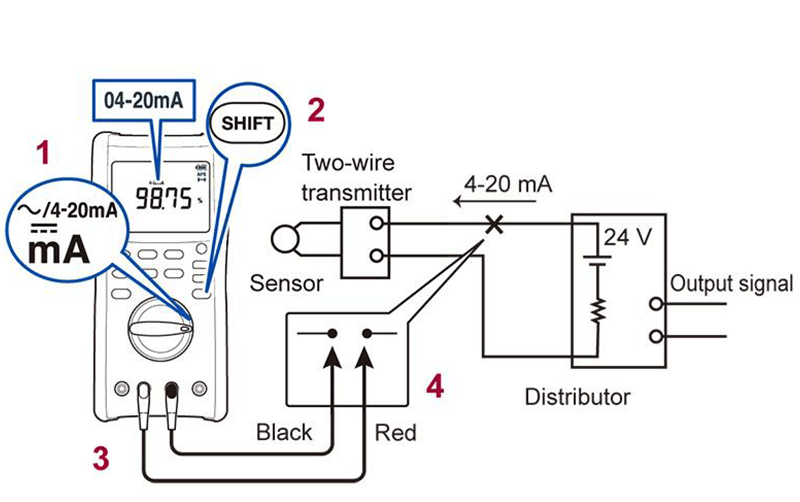
Using digital multimeters (DMMs): Measuring DC current (4 to 20 mA)
To measure current in a DC circuit, set up the digital multimeter as described below. The digital multimeter should be connected in series between the load side and the power supply side of the circuit by cutting the wire indicated with an “X” in the figure.
1. Rotary switch position: “1” in figure
2. Control key operation: “2” in figure
3. Test lead connections to digital multimeter: Black (negative) to COM and red (positive) to μA mA (“3” in figure)
4. Test lead connections to circuit: Black to sensor side and red to power supply side (distributor side) (“4” in figure)
Caution: Shut off the supply of power to the circuit being measured before measurement and then turn it back on after connecting the digital multimeter. Exercise care not to apply a voltage (i.e., not to connect the digital multimeter in parallel with the power supply). Check the maximum current value that the digital multimeter can measure and only use it to measure circuits with currents that are less than or equal to that value.
*This description uses the DT4282 for explanatory purposes. Please check the product specifications for other models as specifications and settings vary.
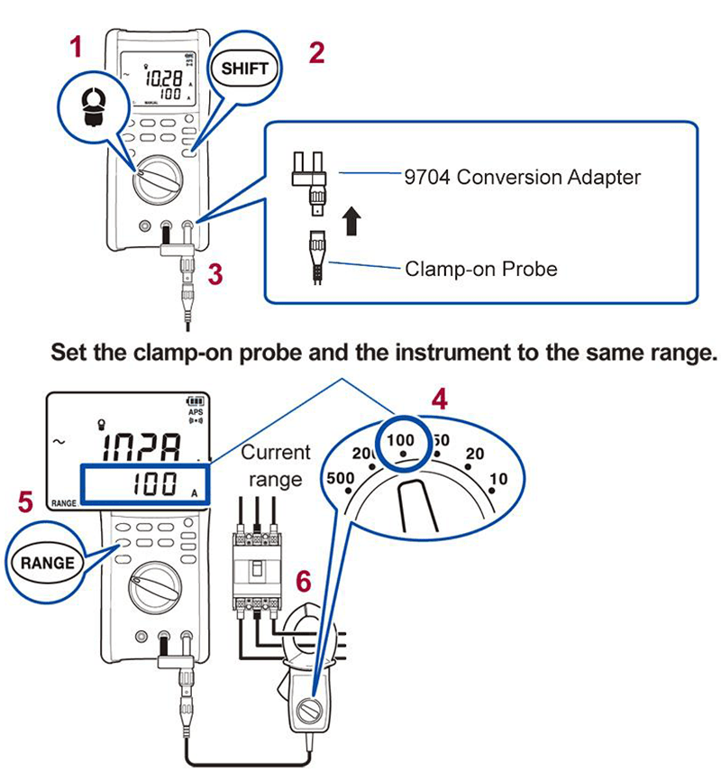
Using digital multimeters (DMMs): Measuring AC current with a clamp-style sensor
To measure current in an AC circuit using the digital multimeter with a clamp-style sensor, set up the digital multimeter as follows and clamp the sensor around the wire being measured:
1. Rotary switch position: “1” in figure
2. Control key operation: “2” in figure
3. Conversion adapter connections to clamp-style sensor: “3” in figure
Conversion adapter connections to digital multimeter: Black (negative) to COM and red (positive) to VΩ
4. Clamp-style sensor current range setting: “4” in figure
5. Digital multimeter range setting: “5” in figure (Set with the RANGE key to reflect the clamp-style sensor’s range.)
6. Clamp sensor connections: “6” in figure
Caution: If the clamp-style sensor’s range changes during measurement, the digital multimeter’s range must be changed to reflect the new value.
*This description uses the DT4282 for explanatory purposes. Please check the product specifications for other models as specifications and settings vary.
Using digital multimeters (DMMs): Convenient functions
Auto hold function: This function automatically stops updating the measured value after the leads have been placed in contact with the circuit under test so that you can write down the measured value. Then it automatically resumes updating the measured value after the test leads have been placed in contact with another measurement point, before once again stopping updating the measured value. (Press and hold the HOLD key for at least 1 sec.)
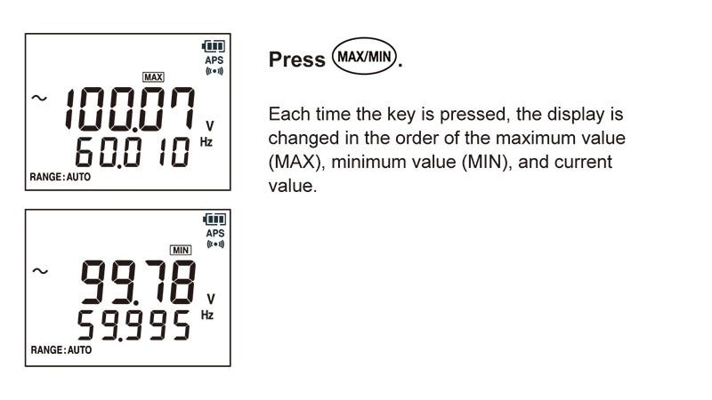
Recording function: This function records the maximum and minimum measured values. (Press the MAX/MIN key.)
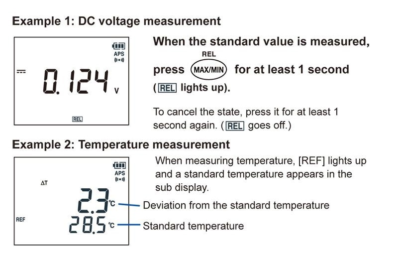
Relative value function: This function measures the amount of variation from a reference value. (Press and hold the MAX/MIN key for at least 1 sec.)
"Product List" of the digital multimeters, please refer to here.
Using digital multimeters (DMMs): Zero-adjustment
For voltage, current, or resistance measurement, set up the digital multimeter as follows:
1. Rotary switch position: Set to the function for which you wish to perform zero-adjustment (“1” in figure).
2. Test lead connections to digital multimeter: Black (negative) to COM and red (positive) to VΩ (for measurement other than current) or black (negative) to COM and red (positive) to A or μA/mA (for current measurement) (“2” in figure)
3. Test lead status: Shorted (“3” in figure)
4. Zero-adjustment: Press and hold the MAX/MIN key for at least 1 sec. (“4” in figure).
For capacitance measurement, set up the digital multimeter as follows:
1. Rotary switch position: (“1” in figure)
2. Test lead connections to digital multimeter: Black (negative) to COM and red (positive) to VΩ (“2” in figure)
3. Test lead status: Open (“3” in figure)
4. Zero-adjustment: Press and hold the MAX/MIN key for at least 1 sec. (“4” in figure)
"Product List" of the digital multimeters, please refer to here.