How to use digital multimeters (DMMs) properly and how to choose a safe multimeter
Overvoltage accidents caused by impulse voltage
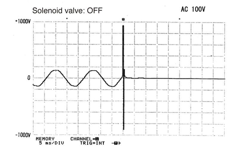
The figure illustrates the waveform characterizing the type of overvoltage that occurs when a solenoid valve operates. In this example, you can see that an impulse voltage of close to 1000 V was generated on the 100 V AC line. Impulse voltages such as this one can occur in manufacturing plants with numerous inductive loads or in the event of a lightning strike near a location where a multimeter is in use.
Measurement categories
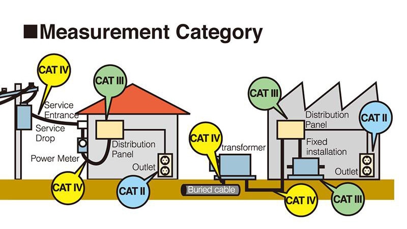
IEC 61010-1, an international standard on multimeter safety, sets forth the measurement categories shown in the figure. Below is a list of multimeters and other measuring instruments that deliver adequate capacity for each category. (For Hioki products, this type of information is available in product catalogs and the Hioki website.)
Card HiTester 3244-60: CAT III (300 V), CAT II (600 V)
Digital Multimeter DT4256: CAT IV (600 V), CAT III (1000 V)
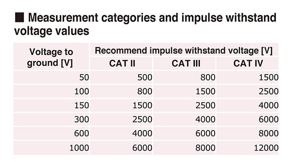
For an instrument to be used in a given measurement category, it must have adequate capacity to withstand the impulse voltage (see table) that can be expected based on the location of use (CAT IV, CAT II, or CAT II) and its voltage relative to ground (circuit voltage).
For example, CAT II (300 V) multimeters are required to be able to withstand an impulse voltage of 2500 V based on a voltage to ground of 300 V. In locations (i.e., categories) such as industrial manufacturing lines where a large impulse voltage described above is possible, it’s good practice to choose a multimeters with as high a measurement category as possible. A detailed description of each category follows.
CAT II: From the power plug of a device connected to an electrical outlet to the device’s power supply circuit
CAT III: Circuits between a distribution panel and the power supply wiring and power supply circuit of a device connected directly to a power source (for example, fixed equipment) and circuits between the distribution panel and electrical outlets
CAT IV: Buildings’ lead-in circuits and circuits between the service entrance and a power meter or distribution panel
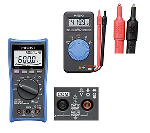
"Product List" of the digital multimeters, please refer to here.
Voltage input to the digital multimeter’s current measurement circuit
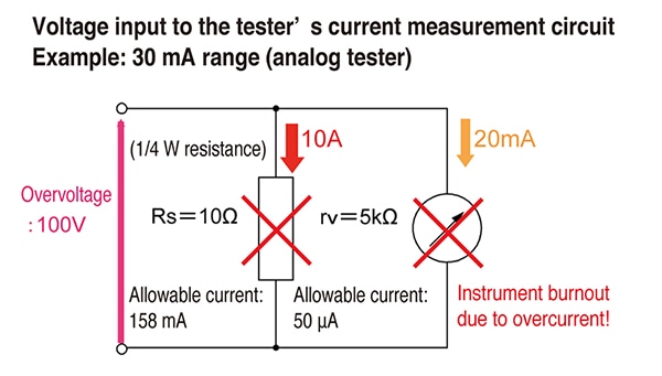
When using a digital multimeter to measure current, the multimeter should be connected in series with the circuit being measured. To minimize instrument loss (resistance) caused by connecting the digital multimeter, the multimeter’s current measurement circuit is designed to have low impedance.
If the digital multimeter is mistakenly connected in parallel to the circuit’s power supply, the supply voltage will be applied across the multimeter’s terminals, causing an overcurrent to flow and the instrument to burn out.
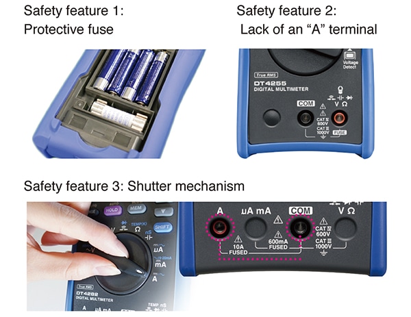
To prevent such damage, most multimeters incorporate a protective fuse. Additionally, some products intentionally omit a current terminal (“A” terminal) or incorporate a mechanism linked to the rotary switch so as to prevent a test lead from being inadvertently connected to the wrong terminal.
"Product List" of the digital multimeters, please refer to here.
Voltage input to the digital multimeter’s resistance measurement circuit
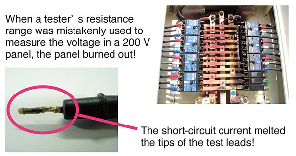
Because the digital multimeter’s resistance measurement circuit has low input impedance, application of a voltage across the test leads could burn out the instrument by causing an overcurrent to flow inside it, and the resulting short-circuit could in turn cause the distribution panel to burn out.
Hioki digital multimeters have an internal overcurrent protection circuit that minimizes any overcurrent caused by voltage input, and they are designed to withstand an overvoltage for up to 1 minute.
Accidents caused by shorting the test leads
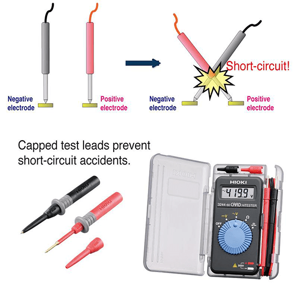
Use of test leads with long metal tips can cause a short-circuit accident when measuring voltage.
All Hioki digital multimeters use capped test leads that have a shorter exposed metal area at the tip.

