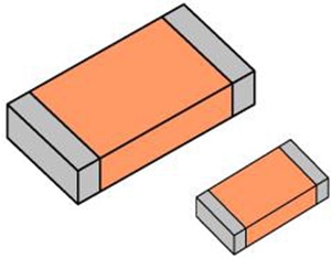
Multi-layer Ceramic Capacitors (MLCC)
What are Multi-Layer Ceramic Capacitors (MLCC)?
MLCC stands for Multi-Layer Ceramic Capacitors. There are two types of MLCC: a high-dielectric-constant type whose capacitance varies with the measurement voltage and a temperature-compensated type whose capacitance does not vary. The measurement conditions used when defining capacitance are set forth by separate JIS standards for temperature-compensated and high-dielectric-constant MLCCs.
Setting example of measurement conditions
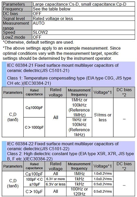
| Parameters | Large capacitance:Cs-D, small capacitance:Cp-D | |||||||||||||||||||||
| Frequency | See the table below | |||||||||||||||||||||
| DC bias | OFF | |||||||||||||||||||||
| Signal level | Rated voltage or less | |||||||||||||||||||||
| Measurement range | AUTO | |||||||||||||||||||||
| Speed | SLOW2 | |||||||||||||||||||||
| LowZ mode | OFF | |||||||||||||||||||||
IEC 60384-21 Fixed surface mount multilayer capacitors of ceramic dielectric(JIS C5101-21) Class 1: Temperature compensating type (EIA type C0G, JIS type CH etc.)(IEC30384-21)
| Parameters | Rated capacitance | Rated voltage | Measurement frequency | Voltage*1 | DC bias *2 | |||||||||||||||||||||||||
| C,D(tanδ) | C≦1000pF | All | 1MHz or 100kHz (Reference 1MHz) | 5Vrms or less | _ | |||||||||||||||||||||||||
| C>1000pF | 1kHz or 100kHz (Reference 1kHz) | |||||||||||||||||||||||||||||
IEC 60384-22 Fixed surface mount multilayer capacitors of ceramic dielectric(JIS C5101-22) Class 2: High dielectric constant type (EIA type X5R, X7R, JIS type B, F etc.)(IEC30384-22)
| Parameters | Rated capacitance | Rated voltage | Measurement frequency | Voltage*1 | DC bias *2 | |||||||||||||||||||||||||
| C,D(tanδ) | C≦100pF | All | 1MHz | 1.0±0.2Vrms | _ | |||||||||||||||||||||||||
| 100pF<C ≦10μF | 6.3V or more | 1kHz | 1.0±0.2Vrms | |||||||||||||||||||||||||||
| 6.3V or less | 1kHz | 0.5±0.2Vrms | ||||||||||||||||||||||||||||
| C>10μF | All | 100Hz or 120Hz | 0.5±0.2Vrms | |||||||||||||||||||||||||||
*1 The measurement voltage (i.e., the voltage applied to the sample) can be calculated based on the open-terminal voltage, the output resistance, and the sample’s impedance.\t
*2 CV mode is convenient when measuring a sample whose impedance is unknown and when measuring multiple samples that exhibit a large degree of variability.
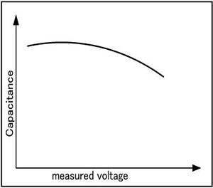
High-dielectric-constant capacitors
Capacitors bearing temperature characteristics such as B, X5R, and X7R use high-dielectric-constant materials.
While high-dielectric-constant capacitors can deliver high capacitance in a small package, their capacitance tends to vary greatly with the measurement voltage and temperature.
Instruments for Mass Production Applications
Model | Measurement frequency | Features |
120Hz,1kHz | Ideal for large capacitance inspection | |
1kHz,1MHz | Ideal for small capacitance inspection, high repeatability |
For more information, please see the individual product catalogs.
Complete Lineup of LCR Meters and Impedance Analyzers
Instruments for Research & Development Applications
| Model | Measurement frequency | Features | ||||||||||||||||||||||||||||
| IM3570 | DC,4Hz to 5MHz | Frequency sweep with analyzer mode | ||||||||||||||||||||||||||||
For more information, please see the individual product catalogs.
Selecting Parameter, Cs or Cp
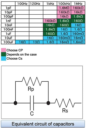
Impedance according to frequency (when D is sufficiently small): please see table on right.
Equivalent circuit of capacitors:
Large capacitance capacitors: Rp can be ignored since impedance of C is low. Select series equivalent circuit modes.
Small capacitance capacitors: Rs can be ignored since impedance of C is high. Select series equivalent circuit modes.
Generally speaking, series equivalent circuit mode is used when measuring low-impedance elements (approximately 100Ω or less) such as high-capacity capacitors, and parallel equivalent circuit mode is used when measuring high-impedance elements (approximately 10 kΩ or greater) such as low-capacity capacitors.
An actual capacitor will behave as though Rs and Rp have been connected in series and in parallel, respectively, with the ideal capacitor C, as in the figure. Rp is usually extremely large (megaohm-order or greater), and Rs is extremely small (several ohms or less). An ideal capacitor’s reactance can be calculated using the following equation based on its capacitance and frequency: Xc=1/j 2πf C[Ω]. When Xc is small, the impedance when Rp is placed in parallel can be considered to be approximately equal to Xc. On the other hand, because Rs cannot be ignored when Xc is small, the overall setup can be treated as a series equivalent circuit with Xc and Rs. By contrast, when Xc is large, Rp cannot be ignored but Rs can, so the setup can be treated as a parallel equivalent circuit.
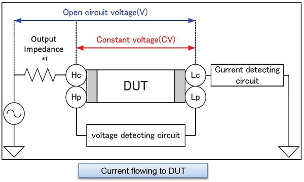
Open-Circuit Voltage Mode (V) and Constant Voltage Mode (CV)
The no-load voltage is the voltage at the Hc terminal when no sample is connected. The voltage applied to the sample is the result of dividing the no-load voltage by the output resistance and the sample.
In constant-voltage (CV) mode, the operator sets the voltage across the sample. The IM35xx reads the voltage monitor value and generates a CV by applying feedback in software. Since the 3504-xx generates a CV in hardware (using an analog circuit), that instrument is capable of constant-voltage measurement at high speeds. Although the 3506-10 offers only no-load voltage (V) mode, it has lower impedance than other models for samples for which the open-terminal voltage is approximately equal to the measurement voltage due to its low output resistance (1Ω for 2.2 mF and greater ranges at 1 kHz and 20Ω for other conditions).
*1 The output impedance varies depending on the model and on whether low-impedance high-precision mode has been enabled. Please refer to the product specifications in the instruction manual.