How to Use an LCR Meter: Basic Knowledge
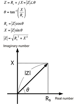
Typical equations for LCR meters
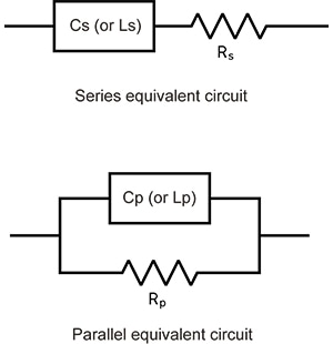
Equivalent circuit mode
LCR meters calculate Z and θ by measuring the current flowing to the measurement target and the voltage across the measurement target’s terminals. They then calculate measurement parameters such as L, C, and R from the Z and θ values.The equations used to calculate these measurement parameters vary depending on whether the instrument is operating in series equivalent circuit mode or parallel equivalent circuit mode.
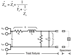
Open correction and short correction
The test fixture used when measuring a target has residual components and can be expressed using an equivalent circuit such as that shown in the figure below. Consequently, the measured value Zm is expressed using an equation that contains these residual components, as shown below. To calculate the true value Zx, it is necessary to calculate the open residual component and short residual component and then correct the measured value. These correction processes are known as open correction and short correction, respectively, and LCR meters include functionality for performing both.
Zm:
Measured value
Zs:
Short residual impedance (Rs: residual resistance; Ls: residual inductance)
Yo:
Open residual admittance (Go: residual conductance; Co: stray capacitance)
Zx:
True value (measurement target’s impedance)
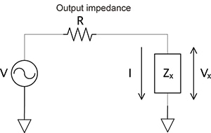
Measurement signal level
The measurement signal output from the LCR meter is voltage-divided between the output impedance R and the measurement target Zx. Thus the set measurement signal level V is not applied as-is to the measurement target Zx. LCR meters have three measurement signal modes.
Open-voltage (V) mode:
The user sets the measurement signal level V in the figure. This value is the voltage when the measurement terminals are in the open state.
Constant-voltage (CV) mode:
The user sets the value Vx in the figure (the voltage between the measurement target Zx’s terminals). This mode is used when measuring targets that exhibit voltage dependence, for example MLCCs with a high dielectric constant.
Constant-current (CC) mode:
The user sets the value I in the figure (the current that flows to the measurement target Zx). This mode is used when measuring measurement targets that exhibit current dependence, for example inductors with cores.