How to Measure Inductance and other characteristics of a Coil or Inductor
This article will give practical and theoretical advice on how to measure the inductance of coils or inductors. Although the article will refer to functions and specifications based off of Hioki’s LCR meters and impedance analyzers that are listed below, much of the advice can be applied to similar products as well.
Table 1: Mass Production Applications
| Model | Measurement Frequency | Features |
|---|---|---|
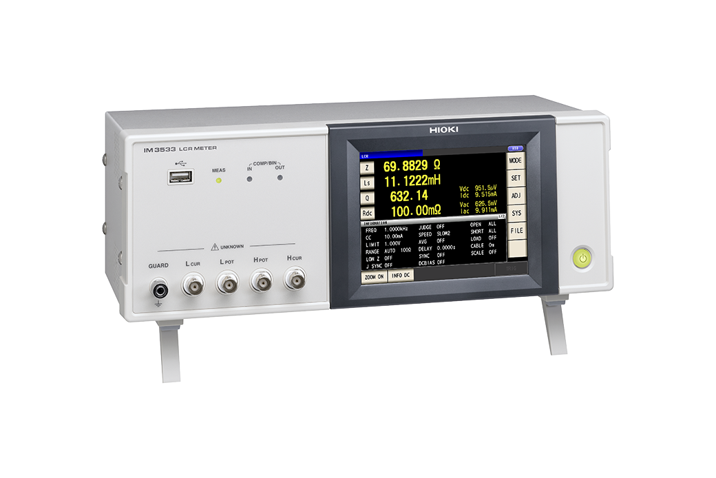
| IM3533 | DC, 40 Hz to 200 kHz | Temperature correction function of Rdc |
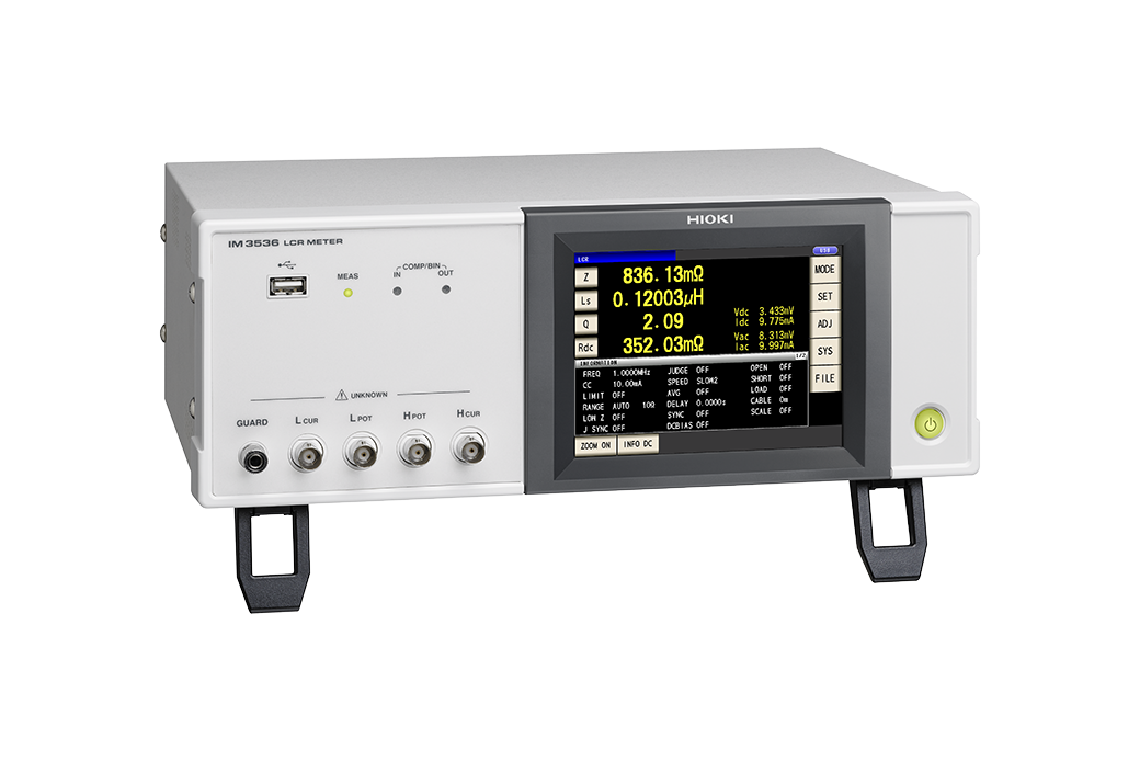
| IM3536 | DC, 4 Hz to 8 MHz | Standard model, high-speed, highly stable, cost-effective analyzer |
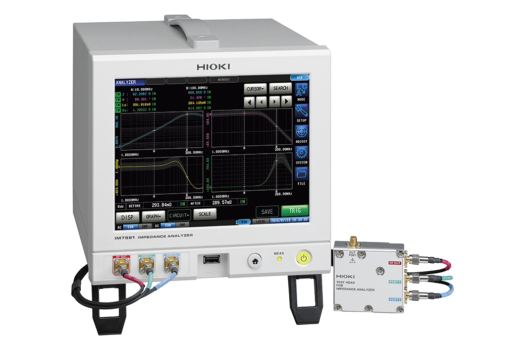
| IM7581 | 100 kHz to 300 MHz | High-speed measurement of coils for high frequency |
Table 2: Reasearch and Development
| Model | Measurement Frequency | Features |
|---|---|---|
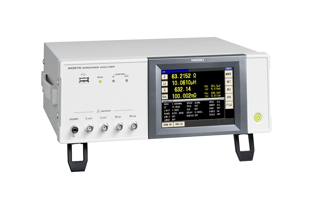
| IM3570 | DC, 4 Hz to 5 MHz | Frequency sweep with analyzer mode |
Before we get started... the core issue
Before we get into how to measure coils or inductors, there is one important distinction of coil types that must be addressed—the “core issue,” one may say. This discussion is important because coil types as it refers to the core have a definite influence on measurement. Coils may be coreless (having an “air core” or a core made of a non-magnetic material), or they may have a core made of a magnetic material such as ferrite or iron. When measuring inductance, knowing the type of core is important because the amount of current flowing through the coil will affect the inductance of the two types differently.
Measurement settings example
Below is an example of an LCR meter’s settings when set manually for measuring the inductance of a common coil. (Optimal settings will vary coil-by-coil.)
Table 3: Measurement settings
| Parameters | Ls, Q, Rdc |
|---|---|
| Frequency | Self-resonant frequency or less |
| DC bias | OFF (cannot measure when setting ON) |
| Signal level | CC (constant current) mode, rated current or less |
| Measurment range | AUTO |
| Speed | SLOW2 |
| LowZ mode | OFF |
Setting the measurement frequency
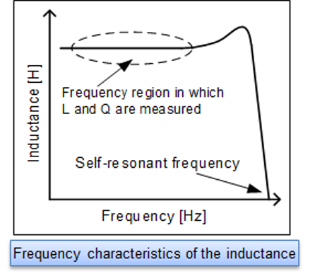
The phenomenon of LC resonance with the coil’s own inductance and parasitic capacitance is known as self-resonance. The frequency at which self-resonance occurs is known as the “self-resonant frequency.” When evaluating coils, be sure to figure out the self-resonant frequency and measure L and Q at a frequency that is sufficiently lower than the self-resonant frequency. This frequency can be determined by actually making measurement and finding a frequency ranging in which the inductance flat-lines (see Fig. 1).
A coil’s impedance, which generally speaking increases with frequency, can be calculated using the following equation:
Z = j2πfL
To measure inductance efficiently while varying the frequency, set the measurement range to AUTO. However, the best way to measure inductance with a higher degree of precision, set the frequency in the aforementioned frequency range in which the inductance consistent.
Setting the measurement current level
The measurement current can be calculated from the open-terminal voltage, the instrument’s output impedance, and the measurement target’s impedance. In order to calculate this, one can use an approximation of the coil’s impedance.
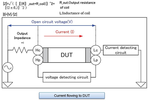
- *1:The output impedance varies depending on the LCR Meter model and on whether the low-impedance high-precision mode has been enabled. Please refer to the product specifications in the instruction manual.
Also important is to set the measurement voltage so that the rated current of the coil is not exceeded.
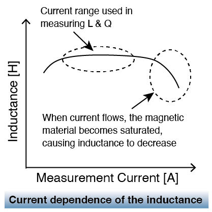
When measuring a coil that exhibits current dependence (i.e. a coil with a magnetic core), one must set the instrument to output a current level such that the magnetic core is not saturated. One can determine the right current level by, yet again, actually measuring inductance—but this time varying the current level. The current level in which the inductance flat-lines, is once again the level that should be used.
When measuring a coil that does not exhibit current dependence (i.e. an air coil or non-magnetic coil), it is recommended to set the instrument to the current level with the best accuracy. For the IM3500 series, the best accuracy is achieved with the V mode’s 1 V setting. With the IM7580 series, the measurement signal level is the setting with the best accuracy is +1 dBm.
When measuring a coil with a magnetic core or a coil with a low rated current, the IM3500 series’ CC (constant current) mode is convenient. The measurement current is controlled via software so that it remains constant.
Selecting Ls or Lp
Generally speaking, a series equivalent circuit mode (Ls) is used when measuring low-impedance elements (approximately 100 Ω or less), and a parallel equivalent circuit mode (Lp) is used when measuring high-impedance elements (approximately 10 kΩ or greater). Fig. 4 gives a ball-park image of which equivalent circuit to use (when the coil’s dissipation factor D is sufficiently small). When the appropriate equivalent circuit mode is unclear, for example when measuring a sample with an impedance from approximately 100 Ω to 10 kΩ, check with the component’s manufacturer.
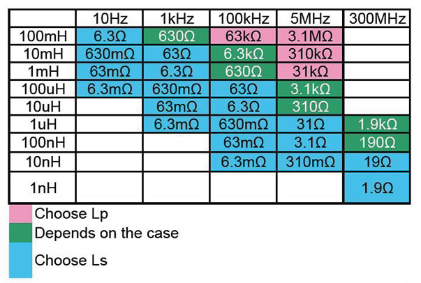 Fig. 4: Impedance according to frequency
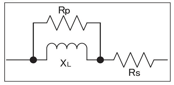
Low-inductance coils: Rp can be ignored since impedance is low. Select series equivalent circuit modes.
High-inductance coils: Rs can be ignored since impedance is high. Select series equivalent circuit modes.
An inductor will behave as though the winding’s copper loss Rs and the core loss Rp have been connected to an ideal inductor L. An ideal coil’s reactance (XL) can be calculated as follows: XL = j2πfL. Although it depends on the magnitude of Rs and Rp, it can be generally stated that low-inductance coils are characterized by a small XL, allowing the impedance when Rp and L are placed in parallel to be treated as roughly equivalent to XL. Rs cannot be ignored since Ls is small, setup can be treated as a series equivalent circuit. By contrast, when the impedance is high, Rp cannot be ignored but Rs can, so the setup can be treated as a parallel equivalent circuit.
Measuring Rdc
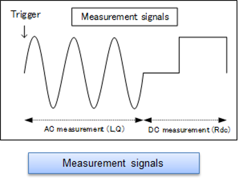
In coil evaluation, inductance L, quality factor Q, and DC resistance Rdc are measured. Instruments such as the IM3533 and IM3536 can measure L, Q, and Rdc without the need to use any other devices. After measuring L and Q with an AC signal, they measure Rdc with a DC signal (see Fig. 5).
*(Rs and Rp are not equal to Rdc. Rs and Rp are resistance values that are measured with an AC signal. They include components such as coil loss and winding resistance, which increases due to conductor skin effects and proximity effects.)
When the winding material has a large temperature coefficient, Rdc will vary with temperature. The IM3533 has temperature correction functionality for Rdc.
Setting the delay time
To reduce measurement error during Rdc measurement, Hioki LCR meters cycle the generated voltage on and off to cancel the internal offset (DC adjustment function). See Fig.6 .
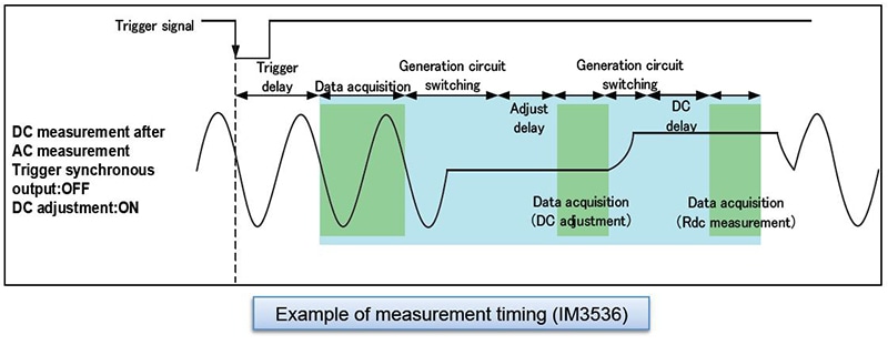
When the voltage being applied to the inductor changes, the output resistance and inductor’s equivalent series resistance and inductance cause transient phenomena (see Fig. 7). Set a sufficiently long delay time during Rdc measurement to ensure that the measurement results are not affected by these phenomena. The name given to the delay time setting varies by model, as does measurement timing. For more information, please see the instruction manual for the model you intend to use. If you are unsure of the appropriate delay time, first set as long a delay time as possible. Then gradually shorten the delay time while verifying that measured values do not exhibit any variability.
![]()
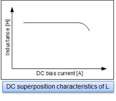
DC superposition characteristics
One type of coil characteristics is DC superposition characteristics, which indicates the extent to which inductance decreases relative to DC current. This becomes an important evaluation item for coils used in circuits that handle large currents such as power supply circuits (see Fig. 8). Although LCR meters like Hioki LCR meters have a DC bias voltage application function, they cannot apply a DC current necessary to do this measurement because this function is designed for use in measuring capacitors. To superpose a DC signal, either use the DC Bias Current Unit 9269 (or 9269-10) and an external power supply, or create your own circuit for the purpose.
Finally
In this way, there are many factors and background knowledge needed to measuring the electric characteristics of coils or inductors. We hope this article was helpful to the reader and ask them to join Hioki in advancing technology for a more profitable and sustainable future.