Current Sensor Working Principle & Characteristics

In this article, we will mainly discuss about current sensors for grid power quality control, which are measured at commercial frequencies (50 Hz, 60 Hz). To learn more about a high-accuracy, wideband current sensor for power measurement and waveform observation, or about the zero flux method, refer to this article.
HIOKI has applied CT (Current Transformer) as a basic technology and realized current sensors with Winding, Hall element, and Rogowski coil methods. In recent years, with the practical application of renewable energy, DC current measurement has also become important, and the demand for the Hall element method is increasing.
- Learn the working principle of current sensors designed for general-purpose measurement.
- Understand the characteristics of each current sensing method to select the corresponding current sensor that best suits your application.
Major types of current sensors for general-purpose measurement:
- 1. Winding method (AC)
- 2. Hall element method (DC/AC)
- 3. Rogowski coil method (AC)
- Comparison table (features, applications, recommended current sensor)
Major types of current sensors for high performance measurement:
How does a current sensor work?
1. Working principle of the winding method (AC)
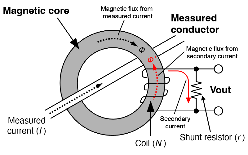
AC current sensors operated on the winding method are the most common type of current sensors used in electrical testing.
- A magnetic flux (Φ) is induced in the magnetic core due to the flow of the alternating current (AC) of the measured conductor (primary side). A magnetic flux (Φ’) due to the secondary current is induced in the secondary coil (N) as a reaction to this primary flux in an effort to cancel it out (back EMF due to self-induction).
- This secondary current flows through the shunt resistor (r), generating a voltage (Vout) at both ends of the shunt resistor.
- This output voltage is proportional to the measured current flowing through the measured conductor (Vout=r/N*I).
2. Working principle of the Hall element method (DC/AC)
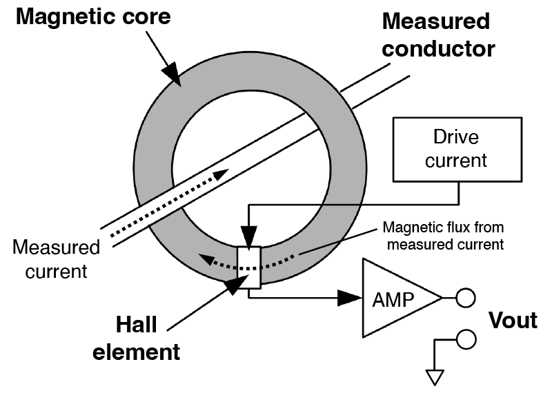
Hall element current sensors are the most basic method of measuring direct current (DC) and alternating current (AC).
- When the magnetic flux (Φ) generated in the magnetic core due to the current flowing in the measuring conductor (primary side) passes through the Hall element inserted in the gap of the magnetic core, a Hall voltage appears according to the magnetic flux due to the Hall effect.
- Since the voltage induced by the Hall effect is small, it is boosted with an amplifier (AMP) before being output.
- This output voltage is proportional to the measured current.
3. Working principle of Rogowski coil method (AC)
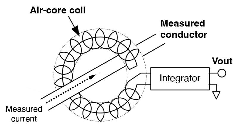
The current sensor using Rogowski coil method is flexible and thin design. The air-core coil structure is resistant to magnetic saturation, so linearity is maintained, making it capable of measuring large currents.
- A voltage is induced in the air-core coil by interlinking the magnetic field produced by the AC current flowing in the conductor being measured (the primary side of the circuit) and the air-core coil.
- This induced voltage is then output as the time derivative (di/dt) of the measured current.
- Also, an output signal proportional to the constant current is obtained by passing it through an integrator.
Features & applications of general purpose current sensors
Comparison table
| Winding method (AC) | Hall element method (DC/AC) | Rogowski coil method (AC) | |
|---|---|---|---|
| Characteristics |
|
|
|
| Application |
|
|
|
| Solutions proposed by HIOKI |
AC FLEXIBLE CURRENT SENSOR CT7046, CT7045, CT7044 CT9667-01, CT9667-02, CT9667-03 (Improved noise resistance) |

Related products
HIOKI designs and produces our own current sensors to pair to measure with power analyzers and power meters.