Insulation Resistance Measurement for the Safety of Solar PV Systems
Introduction
Damaged insulation can result in power loss, equipment overheating, or even fires. Insulation inspections are required to make sure that electrical devices, parts, and equipment used in industrial buildings and facilities do not lose their insulation over time. This aids in preventing electrical shocks and short circuits. The same is true for solar photovoltaic (PV) systems, which need periodic and post-installation insulation inspections.
The IEC62446-1 standard describes two methods for measuring the insulation resistance of a solar PV system.
- 1.To short the positive and negative electrodes of the PV string, and measure the insulation resistance between the shorting point and earth.
- 2.Measuring the insulation resistance between the positive electrode and earth and between the negative and earth separately without shorting.
Measurement that involves a short-circuit
Since solar cells are a type of photodiode and a source of constant current, the positive and negative electrodes can be shorted. Once the electrodes are shorted, a typical insulation meter can accurately measure the insulation resistance. On the other hand, short-circuiting could cause an arc, and there is a high risk of getting an electric shock or getting burned.
To prevent this, the terminals can be short-circuited by a relay with adequate capacity, or a relay with a lower capacity can be used if the measurement is performed at nighttime when the PV modules are not generating power. Keep in mind that there are other risks to consider, such as poor visibility when measuring at night.
Measurement that does not involve a short-circuit
Since this method does not short-circuit the positive and negative electrodes of the solar cell, a relay is also unnecessary and can be easily measured.
When using typical insulation testers, however, there is a risk of getting an inaccurate measurement value. It is caused by measuring the object's having the PV module, which has the electrical potential. A typical insulation tester is designed to measure an object having no electrical potential. Depending on the state of the circuit, the generating PV may affect the measurement and give a result that is different from the actual value.
Cause of an error
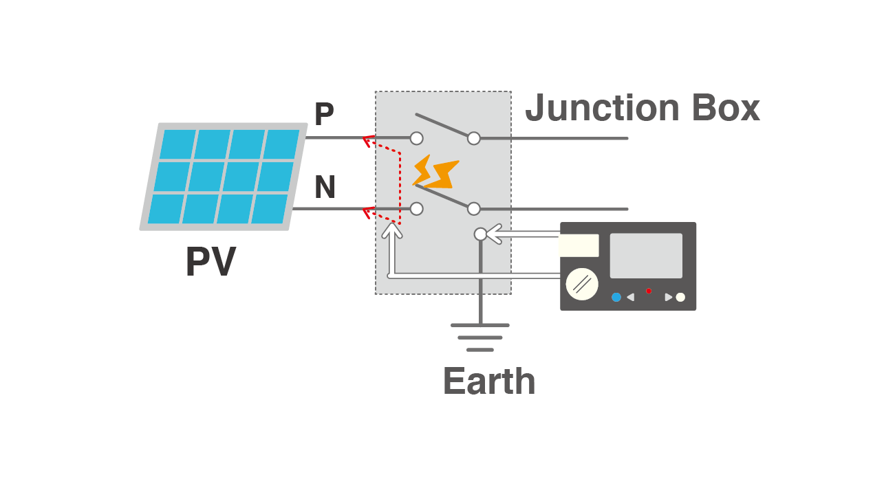
Fig. 1 shows an example of measuring the insulation resistance between the positive electrode and earth while the negative electrode of the PV module has an earth fault. To measure the insulation resistance between the positive electrode and earth, connect the measuring ends of an insulation tester to the positive electrode and earth. In this instance, the negative electrode has an earth fault, meaning that the current generated by the PV modules forms a closed circuit that flows via the earth fault resistance and insulation tester, resulting in an error in measurement. A typical insulation tester outputs the negative test voltage. In this case, the measured current and the PV generated current have the same direction. Thus, the tester detects the higher resistance by adding the PV generated current, and the insulation resistance is displayed lower than the actual insulation resistance value.
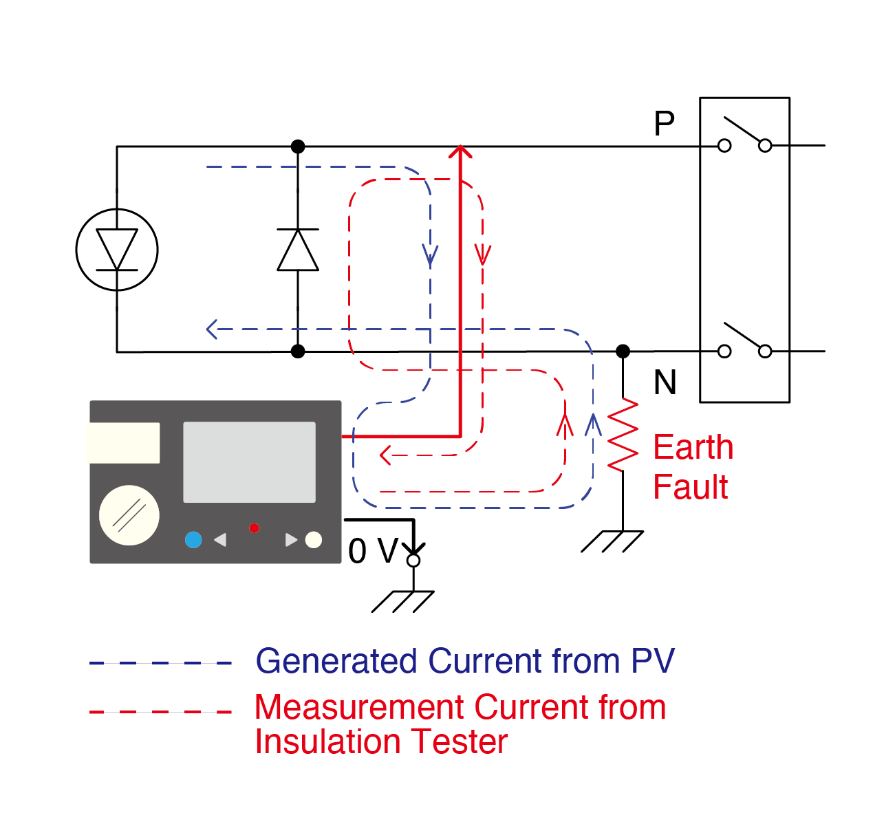 Fig. 1: Example of an earth fault at the negative electrode
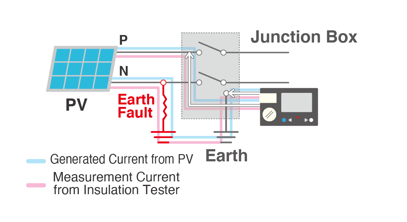
Fig. 2 shows an example of a negative electrode-earth measurement where the positive electrode has an earth fault. In this case, the direction of the measured current and PV generated current becomes the opposite. As a result, the insulation resistance is displayed higher than the actual value by detecting the lower current. Even if an earth fault exists, the insulation resistance might be shown as "infinity" in the worst-case scenario.
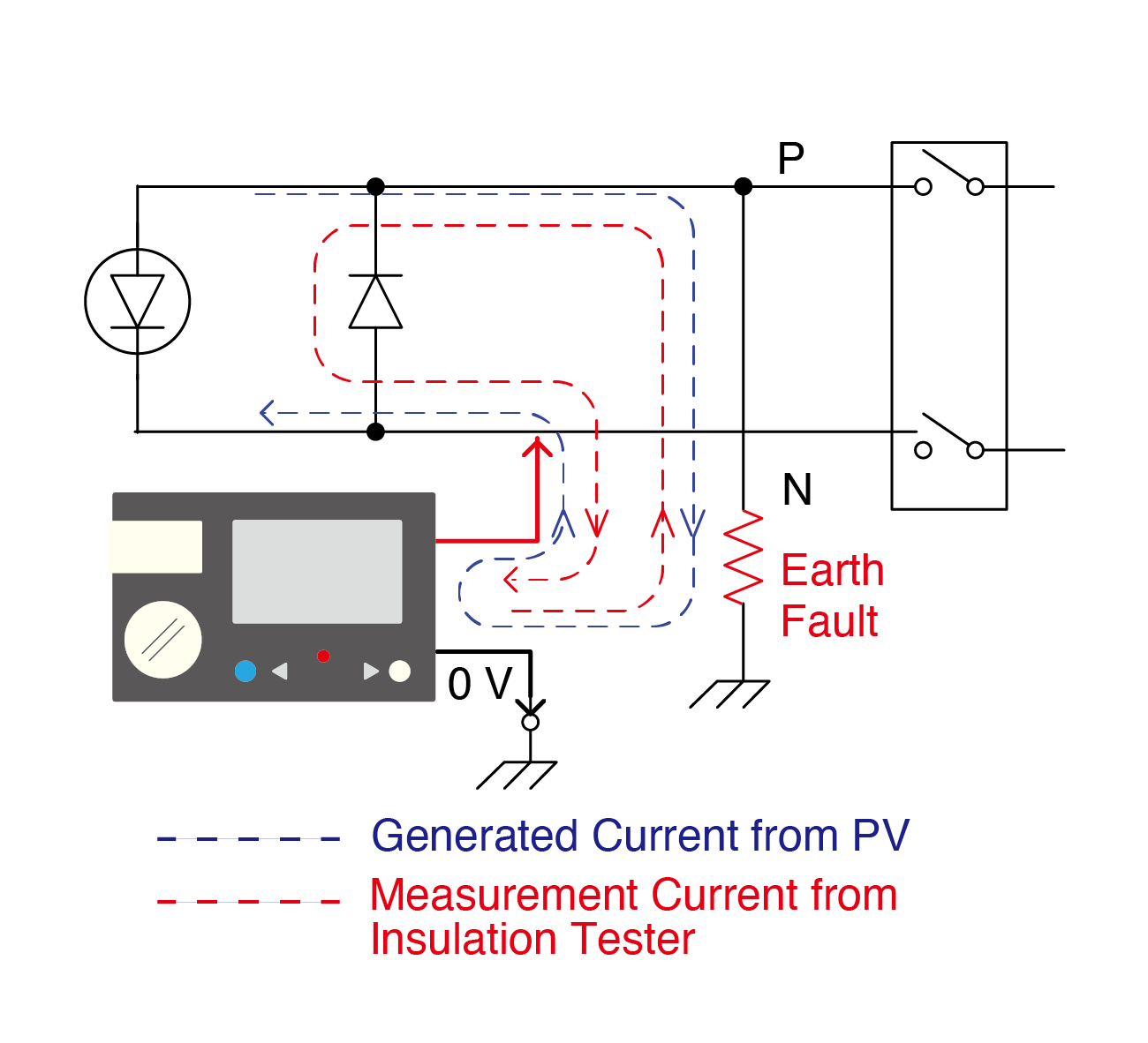 Fig. 2: Example of an earth fault at the postive electrode
These phenomena occur when an insulation tester is connected to form a closed circuit through which the generated current flows. Fig. 3 shows an example of the situation when the standard insulation tester can perform the measurement accurately. In both examples, there is no closed loop to flow the PV generated current. Therefore, the PV generated current does not flow to the tester and does not affect the measurement even if there is an earth fault. Of course, accurate measurement is possible when there is no earth fault.
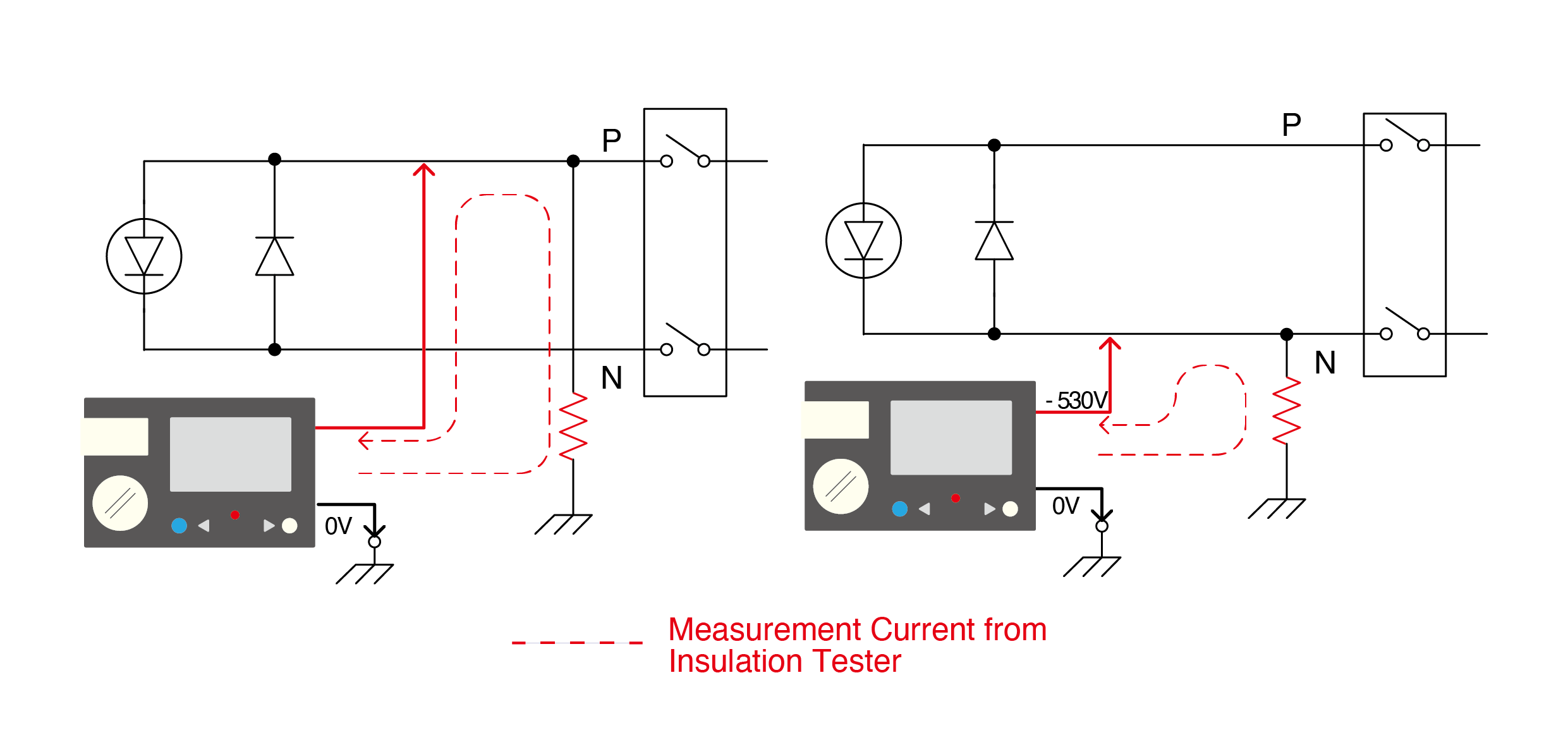
Fig. 3 No closed loop to flow the PV generated current
For safer and more accurate measurements
To safely measure the insulation resistance of PV modules, it is recommended to conduct the measurement with a method that does not involve a short circuit. Also it is important to use a insulation meter that can measure accurately even when the current from the PV modules flows through a closed loop.
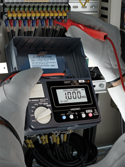
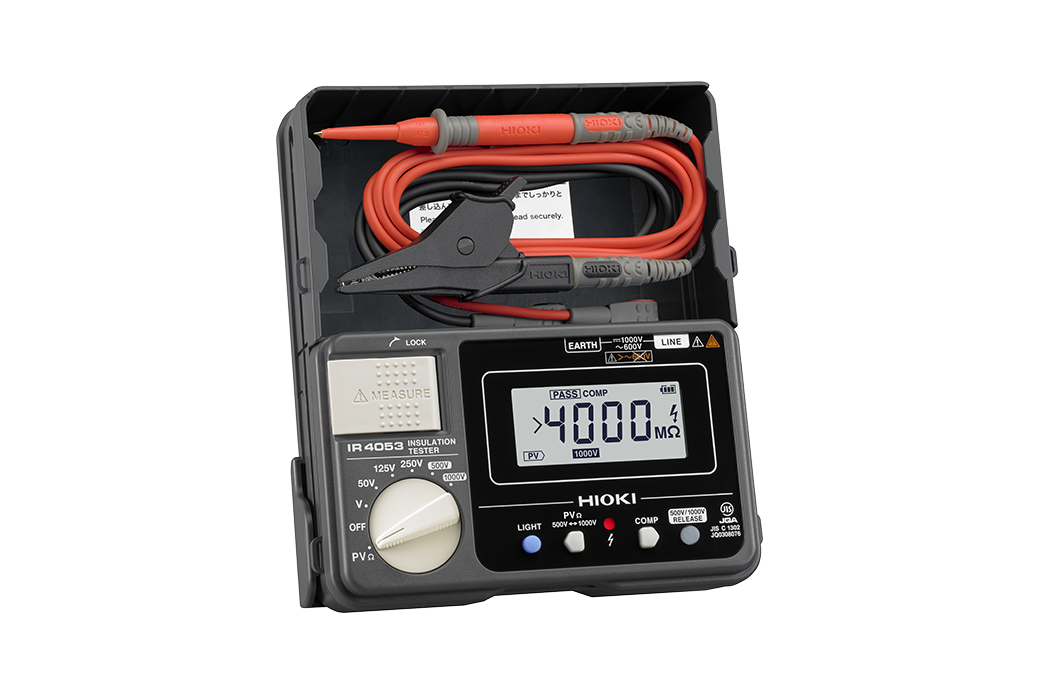
In addition to a normal insulation resistance measurement mode, the Hioki IR4053 also has a mode for measuring PV insulation resistance. It is designed to eliminate the effect of the current generated by the PV module. Therefore, accurate values can be measured even when there is an earth fault in the solar string. The IR4053 has several useful features that facilitate a thorough PV system inspection.
- Perform the insulation measurement in PV mode in just 4 seconds.
- Equipped with an open-circuit voltage measurement function and a polarity determination function. These are useful for polarity testing during PV system installation.
- A PASS/FAIL measurement can be easily judged visually with a comparator function.
Note that in the IEC62446-1 standard, the negative electrode to earth is measured first. However, when measuring insulation with the IR4053, the positive electrode to earth is measured first because the IR4053 outputs a negative test voltage.
Conclusion
As crucial as it is to ensure the solar PV system's safety, it is equally vital to ensure the safety of the person performing the measurements. Therefore, it is better to use an insulation tester equipped with PV mode.