Resistance measurement and low-resistance measurement
How to measure resistance using an analog tester
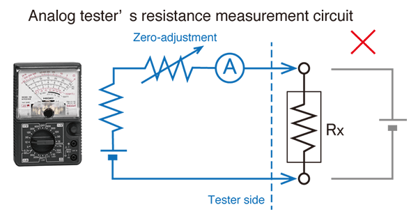
The figure illustrates an analog tester’s resistance measurement circuit.
Before measuring the resistance Rx, short the test leads and perform zero adjustment. This step serves to correct for the tester’s internal resistance value.
If there is any voltage across the Rx circuit, it will result in a short-circuit, so be sure to check.
The analog tester detects resistance values based on the change in ammeter A when connected to the resistance Rx.
Two-terminal measurement with a digital tester and four-terminal measurement with a resistance meter
Most digital testers measure resistance with two terminals. They use a voltmeter to detect the resistance value of resistance R0 while applying a constant current to the measurement target, and the resulting reading includes the wiring resistance r1 and r2. To reduce the impact of the wiring resistance on measured values, it is necessary to perform zero-adjustment by shorting the test leads before measuring the resistance R0.
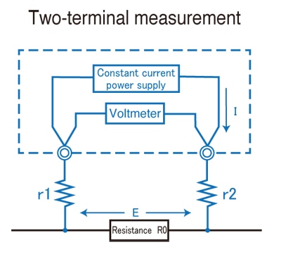
However, this method is not able to eliminate the effects of the contact resistance between the test leads and the measurement target. In addition, it is not able to yield an accurate reading if the resistance R0 is small.
In four-terminal measurement, the circuit that applies the constant current and the circuit that includes the voltmeter are independent up to both ends of the measurement target. As long as zero-adjustment is performed by properly shorting the four test leads, it is possible not only to eliminate the effects of contact resistance, but also to ignore the effects of wiring resistance values r1 to r4.
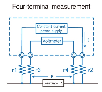
Only certain Hioki products, including some bench-top digital multimeters and resistance meters, use four-terminal measurement to measure DC resistance.
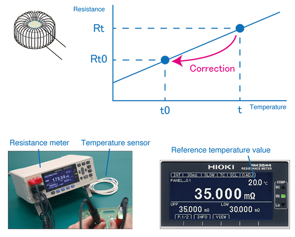
Why is temperature correction important when using a resistance meter?
The resistance of all objects varies with temperature. Since all objects measured with a resistance meter will not necessarily be at the same temperature, it is necessary to eliminate the effects of temperature in order to ensure consistent testing.
A resistance meter's temperature correction function is used to calculate the difference between the temperature value t captured from a temperature sensor that is connected to the instrument and the reference temperature t0. It then applies a correction to the measured resistance value, and provides temperature-compensated the result reflecting the true value.
In order to make use of this functionality, it is necessary to configure the resistance meter with a temperature coefficient.
In the case of annealed copper wire, a coefficient of 0.00393/°C is used. (This is the standard value used by Hioki resistance meters.)
For more information about temperature coefficients for different materials, please see the user manual that came with your Hioki resistance meter.
How to measure the resistance of wires using a resistance meter
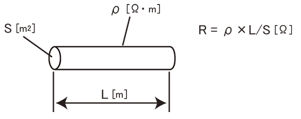
Since the resistance of wires varies with their length, a unit known as conductor resistance (Ω/m) is used to express wire resistance.
The 24 AWG (0.2 sq) cables used to carry weak electrical signals in distribution panels have a conductor resistance of 0.09 Ω/m, while 6 AWG (14 sq) power cables have a conductor resistance of 0.0013 Ω/m, and 150 sq. wires have a conductor resistance of 0.00013 Ω/m.
If S represents area (m2), L length (m), and ρ resistivity (ρ・m) in the figure, the wire’s overall resistance value is given by R = ρ × L / S.