Using Current Measurement to Diagnose Arc Welding Quality and Ensure Traceability
Verifying current waveforms during welding is a key technique for evaluating arc weld quality in an objective manner.
Faced with the possibility that welds could be compromised because the welding current was interrupted or failed to reach the rated value, you can verify whether a welding process was completed appropriately by examining whether the welding current waveform differed from a known-good waveform. In addition to objectively judging weld quality based on the current waveform, you can retain associated records in order to improve quality and reliability through traceability.
This Application Note introduces techniques for measuring current during welding processes and instruments that are suited to such measurements.
Example welding current waveforms
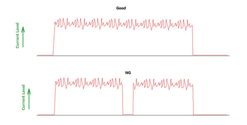
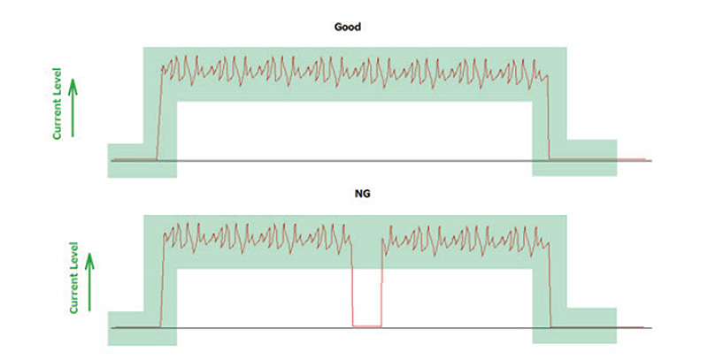
The example waveforms to the right illustrate welding current during non-defective and defective welding processes. An interruption of the welding current will result in a defective process, but it’s not possible to detect such issues if the current waveform is not being observed.
Observing high-speed phenomena that occur at unexpected times is precisely what Memory HiCorders, with their high-speed sampling and high-capacity memory, are designed for. By ascertaining momentary interruptions to the welding current caused by short-circuits and arcing, you can help improve the quality and reliability of welds.
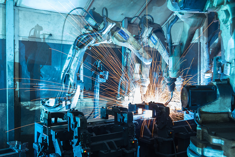
Resolving defects during welding with a Hioki Memory HiCorder
The Memory HiCorder’s waveform judgment function is particularly convenient in process quality control for welding robot lines. You can keep defective parts from advancing to the next process by treating waveforms outside a preconfigured area as anomalous, as shown at right, and automatically stopping the line or determining that a defective part was detected.
Additionally, you can automatically save data and analyze it later to ensure traceability in welding processes and keep issues from recurring.
Below is a procedure for using a Memory HiCorder to easily and safely measure and record the current from an arc welder.
1. Connect a current sensor to the terminal of a current unit that’s been installed in the Memory HiCorder.
2. Affix the current sensor to the ground-side cable that connects the welder to the material being welded.
During welding, a large current–ranging from dozens to thousands of amps–will flow through the cable. Using a shunt resistance to directly input such a current to an instrument would carry risks, but you can measure such currents safely and quickly simply by affixing a clamp sensor to an insulated cable.
3. Set the necessary parameters, including the Memory HiCorder’s input range, measurement speed, and recording length, and then start welding once you’re ready.
You can efficiently record just the data you need when welding starts by setting a recording start condition with the trigger function.
4. If you’re using the waveform judgment function, record a known-good waveform and set the area width for non-defective welds based on that waveform.
Introduction to instrument and devices needed for welding current measurement
A Memory HiCorder used in conjunction with a clamp-type current sensor is ideal for measuring welding current waveforms.
1. A welding current is a continuous current that varies momentarily due to short-circuits and arc discharges, and instantaneous current control is essential in order to minimize the occurrence of spatter. Memory HiCorders can reliably measure uch high-speed phenomena.
2. Data captured by the Memory HiCorder can be saved on the instrument’s internal SSD, USB drive, or memory card, or sent to a server via a LAN connection.
3. An extensive range of current sensors is available, including high-response models that can track precipitous changes, to measure currents of all magnitudes.
These sensors can measure DC currents in particular more safely, and better withstand slow-rising currents and noise, than sen sors that require a shunt resistance.
4. Memory HiCorders offer a variety of trigger functions. The ability to configure triggers based on the measurement purpose at hand, for example to capture currents that fail to reach a rated value, timing discrepancies, or noise, allows you to dependably record anomalous current waveforms.
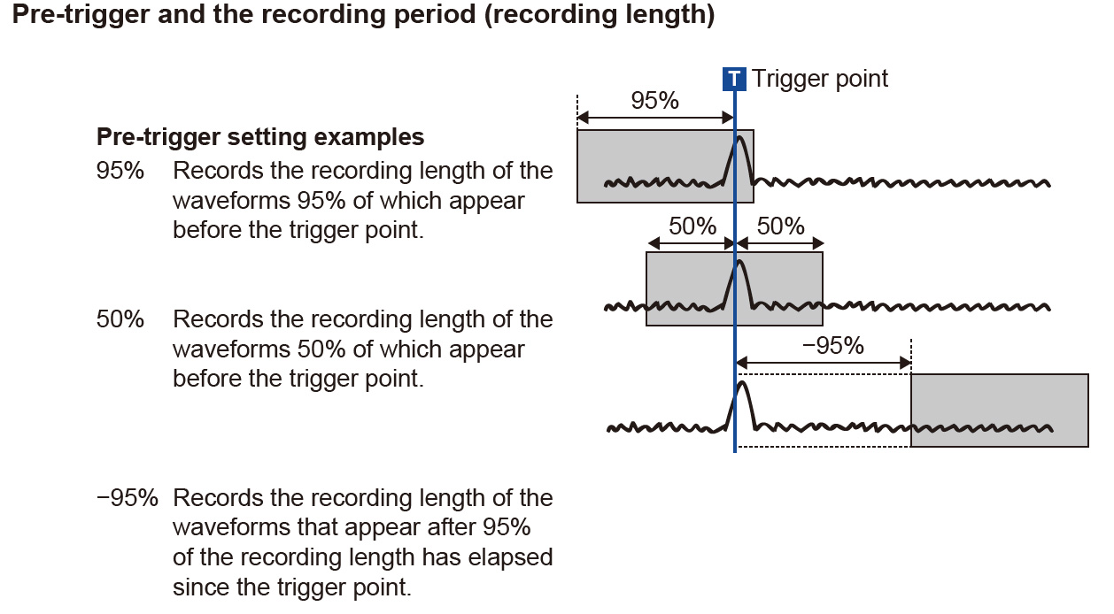
If recording starts after the trigger activates, the instrument could fail to capture important phenomena occurring before the trigger. Memory HiCorders’ ability to capture phenomena occurring before triggers helps avoid such issues.
The instrument’s pre-trigger function lets you record data both before and after triggers to facilitate multifaceted analysis and evaluation.
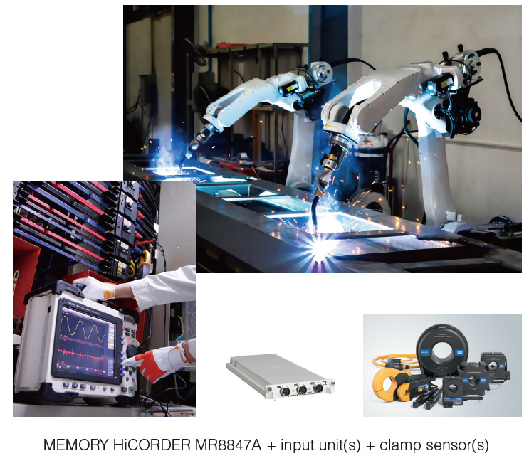
Example combination of recommended instrument and devices
Principal equipment used
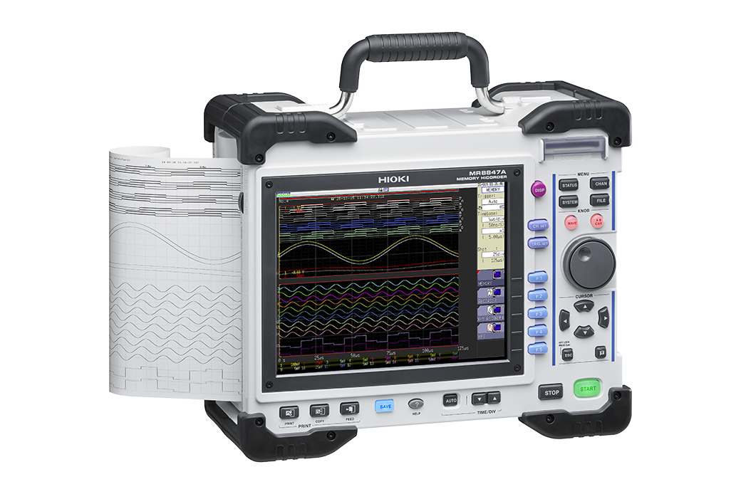
Recorder MEMORY HiCORDER MR8847A
Input Unit 3CH CURRENT UNIT U8977 × 1
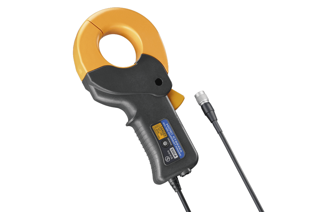
Current Sensor AC/DC CURRENT PROBE CT6845A × 1
*The above is an example combination. Input unit and current sensor recommendations vary with the object under measurement.
It’s important to select the most appropriate input unit and current sensor based on the measurement application and the rating of the object under measurement.
*Precautions
Do not attempt to measure the output voltage of a welder directly. Some welders (for example, TIG welders) apply high frequencies or high voltages that could damage the instrument.
Summary
• A Memory HiCorder with high-speed sampling can be used with an AC/DC high-sensitivity current sensor to diagnose arc welding quality issues while ensuring traceability.
• On welding robot lines, the instrument can help prevent problems and analyze data thanks to multichannel, simultaneous measurement capability that lets you check not only welding current, but also correlations with other parameters like control signals.
Hioki offers recorders that satisfy these requirements as well as an extensive selection of clamp sensors, including DC/AC, high-sensitivity, and wideband models, to meet customers’ needs and resolve their issues.

