Charge/Discharge Testing of High-Voltage Batteries
An Ideal Data Logger for Recording Cells’ Voltage and Temperature Data
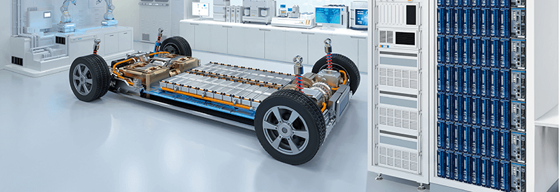
Battery charge/discharge testing is carried out as part of performance tests during battery cell, module, and pack development and during the evaluation stage. This type of testing allows manufacturers to inspect the battery’s charge and discharge performance as well as its service life. It plays an essential role in the development of safe, high-performance batteries and in the verification of finished products’ performance. In battery pack charge/discharge testing, technicians test for anomalous voltage or temperature readings at each cell and evaluate the batteries’ characteristics. Since variability in cell characteristics can lead to a decline in the battery pack’s overall performance, it’s extremely important to ascertain voltage and temperature behavior at the cell level. To reduce charge times and extend vehicle range, manufacturers are developing higher-voltage battery packs for use in electric vehicles (EVs). This article introduces a data logger that’s ideal for charge/discharge testing of standard 400 V battery packs as well as 800 V battery packs, which are already being commercialized.
Data logger performance required by this test
Although the voltage of individual cells in a battery pack is low at about 4 V, measuring cell voltages in an 800 V battery pack, for example, requires an instrument with a maximum terminal-to-earth rated voltage of 800 V DC or greater. An 800 V battery pack consists of about 200 cells that are connected in series. About 400 channels are needed in order to measure all cells’ voltage and temperature.
Measurement capability and performance such as the following are needed in order to perform battery pack charge/discharge testing:
Measurement of high-voltage battery packs
- High insulation performance of measurement instrument
- Expandability of instrument’s channel count
Data reliability
- Ability to capture detailed voltage and temperature data
- Countermeasures to combat noise from nearby devices
Data analysis
Ability to output data in real time
With regard to insulation performance, particular caution is necessary concerning the fact that the voltage across connected measurement modules and between an instrument’s terminals and earth is not the same as the instrument’s withstand voltage. The withstand voltage is the voltage that can be applied to a given target device for 1 minute while powered off without damaging it during withstand voltage testing. Since having a given withstand voltage doesn’t mean that voltage can be applied continuously without problems, even products that advertise a withstand voltage of 800 V are not capable of measuring battery voltages in a setup where a voltage of 800 V is continuously applied across modules or between instrument terminals and earth.
Data loggers that are ideal for use in battery charge/discharge testing
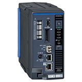
The Hioki Data Logger LR8101 and LR8102 are ideal for use in charge/discharge testing of today’s increasingly high-voltage batteries. Simply combine as many M7100 and M7102 measurement modules as are necessary based on the necessary insulation performance, sampling speed, and channel count.
| Data Logger LR8101 | Data Logger LR8102 |
|---|---|
| Connect up to 10 measurement modules to 1 logger | |
| LAN data transfer | Synchronize up to 10 loggers |
| - | High-speed data transfer (UDP) |
| Voltage/Temp Module M7100 | Voltage/Temp Module M7102 | |
|---|---|---|
| Channel | 15 channels (voltage/temperature) | 30 channels (voltage/temperature) |
| Insulation performance |
|
|
| Sampling rate (data refresh interval) | 5 ms* (when using 1 ch to 8 ch) 10 ms to 10 s (when using 9 ch to 15 ch) | 10 ms (when using 1 ch to 15 ch) 20 ms to 10 s (when using 16 ch to 30 ch) |
*Voltage range only (temperature: from 10 ms)
The Data Logger LR8101 and LR8102 can measure and record the temperature and voltage of individual battery cells in a safe, detailed manner. The loggers can be combined with measurement modules to easily expand the number of input channels to a maximum of 3,000 channels. Thanks to 1500 V DC CAT II insulation performance that’s compliant with the EN IEC 61010 safety standard, these loggers can safely measure high-voltage systems. They can capture detailed voltage fluctuations at high resolution thanks to their maximum sampling speed of 5 ms. Furthermore, the LR8102 is capable of high-speed output of measured data, one datapoint at a time. This capability lets you monitor voltage and temperature data during charge/discharge testing in real time.
There are five reasons why the LR8101 and LR8102 are ideal for use in charge/discharge testing:
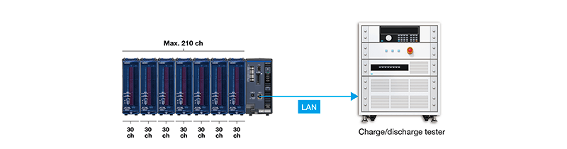
1. The instruments are highly expandable as the number of channels can be easily increased
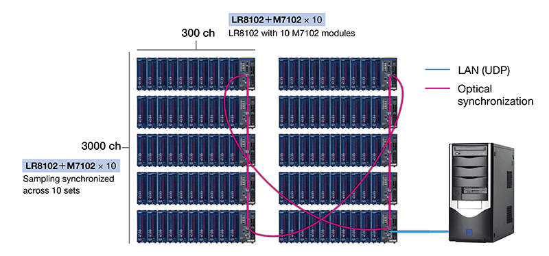
Both the data logger and measurement modules are available in two types. The number of channels can easily be increased by adding modules. Furthermore, if you’re using the LR8102, up to 10 loggers can perform synchronized sampling. By combining the LR8102 with the M7102, you can expand the number of channels to a maximum of 3000. The figure below illustrates a system in which 10 LR8102 instruments, each equipped with 10 MR7102 modules, have been synchronized using optical connection cables (20 ms sampling). (The sampling speed is limited by the number of channels being used.)
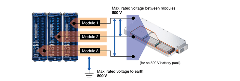
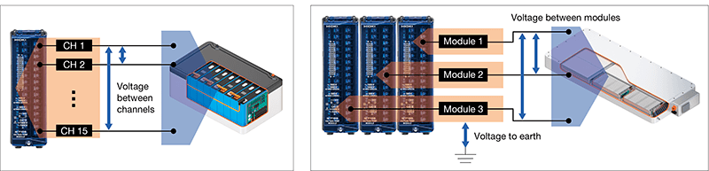
2. Make measurements safely thanks to 1500 V DC CAT II insulation performance that complies with the EN IEC 61010 safety standard
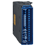
When measuring voltage in battery pack cells or measuring electrode temperature, high voltages will be applied between terminals and earth (between input channels and earth) and between measurement modules. The Hioki Voltage/Temp Unit M7100 uses a newly designed isolation transformer to attain 1500 V DC insulation between input channels and earth. Safety and reliability are assured thanks to the device’s ability to withstand not only steady high voltages, but also transitory voltage surges.
M7100
Maximum rated voltage between channels: 300 V DC
Maximum rated voltage to earth: 1500 V DC, 1000 V AC (CAT II)
Maximum rated voltage between modules: 1500 V DC, 1000 V AC
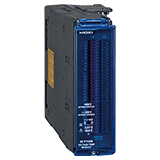
M7102
Maximum rated voltage between channels: 300 V DC
Maximum rated voltage to earth: 600 V DC, 600 V AC (CAT II)
Maximum rated voltage between modules: 600 V DC, 600 V AC
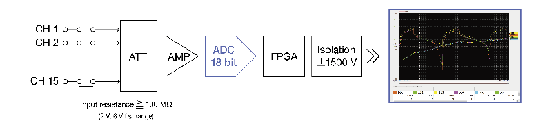
3. Capture voltage fluctuations at high resolution thanks to high-speed sampling capability
The M7100 measurement module provides a maximum sampling speed of 5 ms, while the M7102 provides a maximum sampling speed of 10 ms. (In both cases, the sampling speed differs by the number of channels being used per module.) To ensure battery cell voltage fluctuations can be captured in detail, each modules has an 18-bit resolution AD converter. As a result, modules can be added without compromising the maximum sampling speed. In addition, the modules are designed to provide an input resistance of 100 MΩ in the 2 V and 6 V ranges in order to minimize leakage current from the battery to the data logger. In these ways-especially thanks to their high-speed sampling capability and high resolution-the setup can capture detailed voltage fluctuations.
Measurement resolution and accuracy
When using the 2 V f.s. range: 20 μV resolution and ±1 mV accuracy
When using the 6 V f.s. range: 60 μV resolution and ±3 mV accuracy
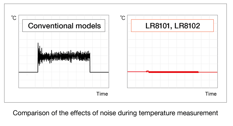
4. Improved noise resistance and stable, accurate measurement
Charge/discharge testers, which handle high voltages and large currents, are prone to generate noise. Consequently, measurement by nearby devices during charge/discharge testing is prone to the effects of noise. The Data Loggers LR8101 and LR8102 deliver high noise resistance. Even in high-voltage, high-frequency noise environments, they’re capable of stable measurement in which measured values don’t shift or fluctuate significantly.
5. Output voltage and temperature data in real time during testing
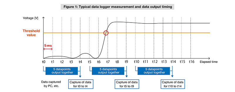
To capture measured data with a battery control simulation system, it’s necessary to output data to the system at high speed. Ordinarily, communications commands are used to send data from data loggers to such systems. The speed at which data can be captured using text commands is limited to a cycle that ranges from tens of milliseconds to several hundred milliseconds.
Figure 1 provides an example of measurement and data output timing using a typical data logger. Although the voltage value exceeds the threshold by t7, that data cannot be acquired until t9.
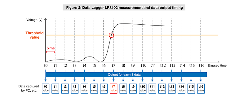
Figure 2 illustrates the timing at which data for measurements made with the Data Logger LR8102 are output. The LR8102 uses the UDP communications protocol, allowing it to output data at high speed. Measurement data is output one datapoint at a time, allowing all data to be analyzed in real time. Even data for t7, when the threshold value was exceeded, can be acquired immediately.
Example data logger setup
Data loggers are combined with measurement modules. The user chooses the type of instrument and the number of modules to connect based on the necessary insulation performance, sampling speed, and channel count. The sampling speed differs by the number of channels being used per module.
Standard application: 400 V battery pack (4 V × 100 cells)
This section introduces an example instrument setup for measuring the voltage and temperature at each cell in a 400 V battery pack and transferring the data to a charge/discharge tester. A single M7102 can measure up to 30 channels. This measurement setup can be implemented at low cost in terms of both investment and space.
Instrument configuration
Data Logger LR8101 × 1
Voltage/Temp Module M7102 × 7
Measurement conditions
Number of channels: 100 voltage + 100 temperature
Sampling speed (data refresh interval): 100 ms
Data transfer interval: 200 ms*
Data communications: LAN-based text command transfer
*The text command transfer data transfer interval is limited by the number of measurement modules in the setup.
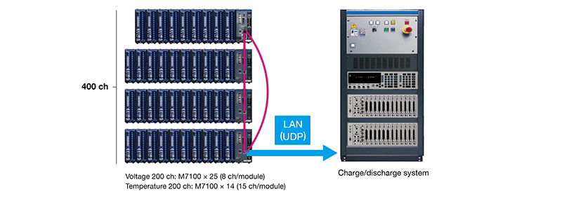
Advanced evaluation system: 800 V battery pack (4 V × 200 cells)
This section introduces an example instrument setup for measuring the voltage and temperature at each cell in a high-voltage 800 V battery pack and transferring the data to a charge/discharge system in real time. LR8102 loggers can be connected with optical cables to synchronize measurements of up to 10 instruments. The M7100 assures safety for high-voltage battery testing with 1500 V DC CAT II insulation performance. In the voltage range, if no more than 8 channels are being used by any given module, measurements are made at a maximum data refresh interval of 5 ms, and all data can be transferred in real time. The battery's total voltage value, which is being monitored by the charge/discharge system, can be monitored with low delay
Instrument configuration
Data Logger LR8102 × 4
Voltage/Temp Module M7100 × 39
Optical Connection Cable L6101 × 4
Optical Connection Cable L6102 × 1
(The optical connection cables are unnecessary if external sampling signals are input in parallel from the charge/discharge tester.)
Measurement conditions
Number of channels: 200 voltage + 200 temperature
Sampling speed (data refresh interval): 5 ms (voltage), 10 ms (temperature)
Data transfer interval: 5 ms
Data communications: UDP-based real-time data transfer
Summary
The Hioki Data Loggers LR8101 and LR8102 and the M7100 and M7102 measurement modules are ideal for use in charge/discharge testing of batteries. Robust insulation performance boosts safety, and reliable measurements and accurate data capture capability provide support for battery back and peripheral system development.
Please visit Hioki's website for more information about these products.
Requests for demonstration units and questions about applications should be directed to your closest Hioki representative through our contact form.