Partial Discharge Testing of Motor Stators Using a Withstand Voltage Tester and Oscilloscope
Partial Discharge Testing of Motor Stators Using a Withstand Voltage Tester and Oscilloscope
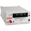
Withstand voltage testing is performed by applying a high AC voltage to insulated areas and checking the insulation’s dielectric strength. Pass and fail judgments are made based on current RMS values. Demand for the ability to monitor waveforms during withstand voltage testing (dielectric strength testing) has been growing in recent years.
Have you ever heard a faint sound caused by discharge during withstand voltage testing? That sound is made by discharges that are not accompanied by sparking. Since this discharge phenomenon does not appear in current values, the stator will pass the withstand voltage test. However, the discharge could cause an insulation failure after the motor has entered the market.
In this application, we attempted to detect partial discharges based on current waveform observations during withstand voltage testing.
Solutions
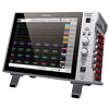
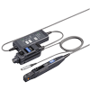
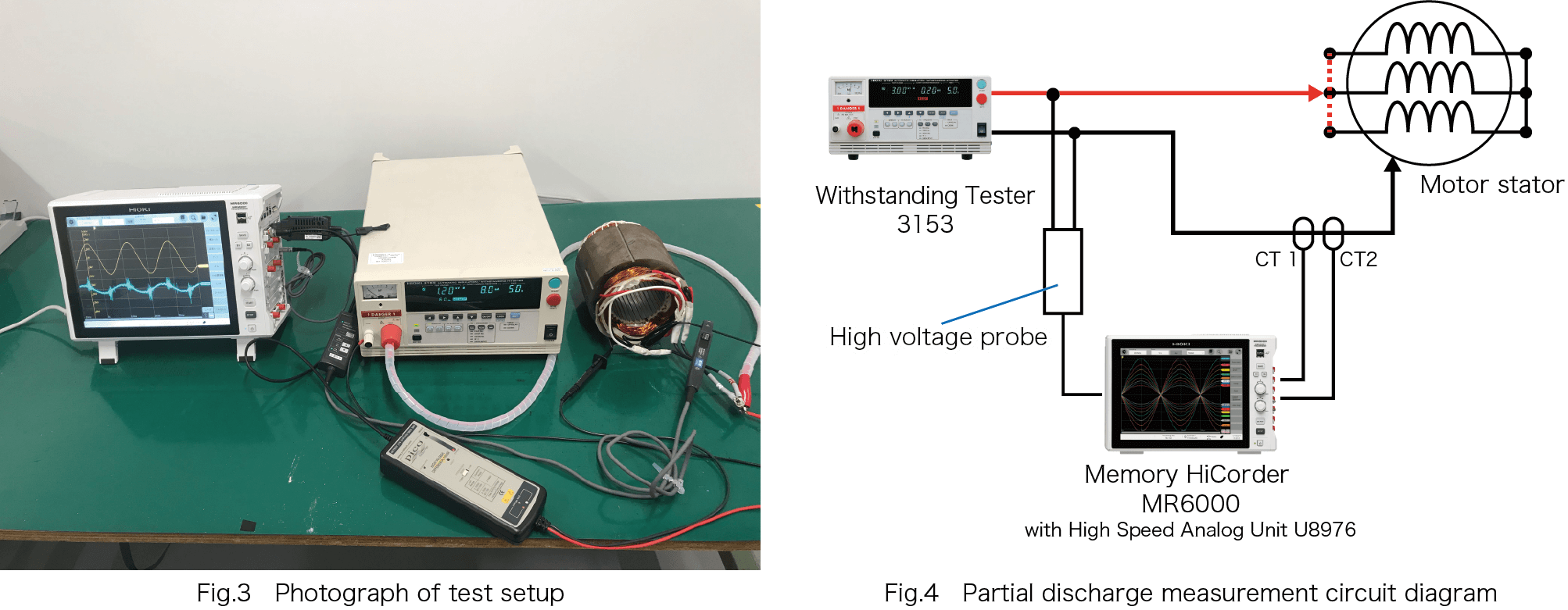
A withstand voltage tester is connected between a coil of a stator that is connected to the neutral point and the ground (Figs. 3 and 4). Two CT probes are attached on the ground side. CT1 measures from DC to 120 MHz, while CT2 measures from 4.8 kHz to 400 MHz. The current waveforms from these two CTs are observed using an MR6000 (similar to an oscilloscope).
Measured data 1
• At a test voltage of 1000 V AC, no change was observed in either the CT1 (light blue) or CT2 (white) waveform.
• At a test voltage of 1400 V AC, partial discharge waveforms were observed for both CT1 and CT2.
• We enlarged the partial discharge waveform at the 1400 V AC test voltage for further observation.
Measured data 2
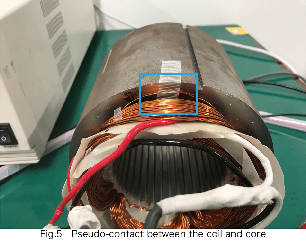
• We placed the coil in contact with the core and observed the current waveform with a test voltage of 1000 V AC.
• Although there was no change when the coil was not in contact with the core, a partial discharge waveform was observed when the coil was in contact with the core.
Summary
• Partial discharges, which cannot be detected using withstand voltage testing alone, can be detected by observing current waveforms during withstand voltage testing.
• In the presence of an insulation defect, the partial discharge starting voltage will be lower.
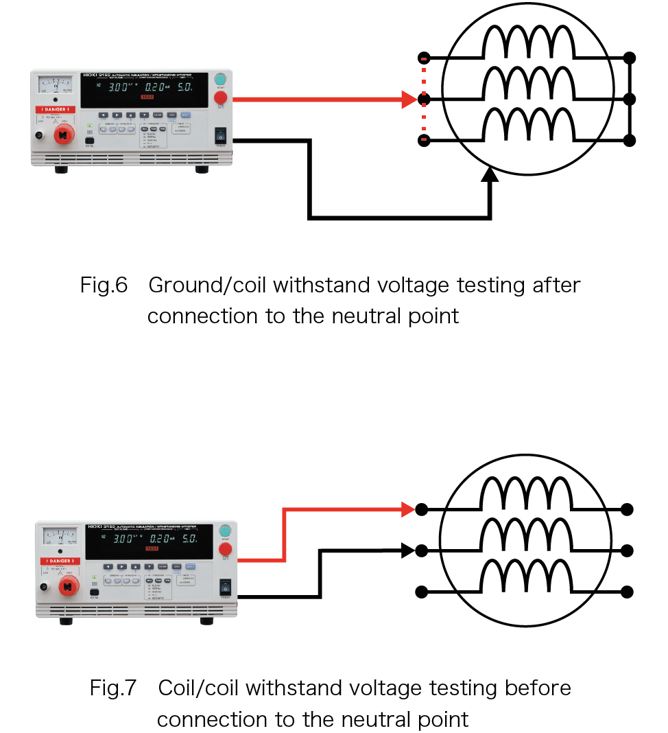
• If the stator has not yet been connected to the neutral point, you can check for partial discharges between coils (Fig.7).
• It may be possible to automate testing using the oscilloscope’s trigger function.
• However, it will be necessary to exercise caution concerning grounding and the noise environment.
Contact Metrology Lab by Hioki for application questions and test requests.