How to Separate Motor Losses and Create Efficiency Maps
Introduction
Electric vehicle motors must deliver high efficiency across a wide range of speeds. Therefore, it is important to create an efficiency map that illustrates how efficiently the motor operates at various rotational speeds and torque levels.
This application note aims to provide readers with a deep understanding of the measurements required to create an efficiency map, and to demonstrate how straightforward the process can be when using Hioki's Power Analyzer PW8001. Step by step, we will guide the reader through the efficiency measurement of a Permanent Magnet Synchronous Motor (PMSM) and explain how to generate efficiency maps by separating losses into copper losses and iron losses, based on the fundamental wave and other frequency components.
Overview of Motor Efficiency and Losses
Motor output and losses
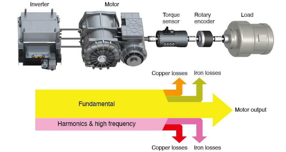
When voltage is supplied from the inverter to the motor, current flows through the motor windings, generating magnetic flux in the stator. This magnetic flux creates a magnetic field that causes the rotor to rotate.
In a Permanent Magnet Synchronous Motor (PMSM), the motor rotates in synchronization with the fundamental wave of the inverter’s output voltage, whose frequency determines the angular speed (ω), directly driving the motor output Pm = τ × ω, where τ is torque.
The Power Analyzer PW8001 accurately measures the fundamental wave output Pfnd, which is converted into mechanical power Pm, with portions consumed as copper losses Pcfnd in the windings and iron losses Pifnd in the core.
Harmonic components of the fundamental wave and high-frequency components, such as those caused by switching frequencies, also result in copper and iron losses. These losses, which we will discuss in more detail later, must be separated using a high-end power analyzer to create accurate efficiency maps and loss maps.
Measuring motor efficiency with the PW8001
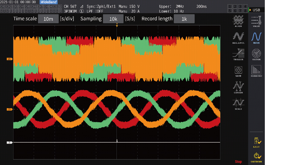
Inverter voltage and current waveforms
When measuring a motor system with a power analyzer, it is possible to measure not only the total output of the inverter but also the output of the fundamental wave alone. By measuring the motor's torque and rotational speed, the motor output can also be determined.
Power analyzers have the capability to internally calculate efficiency and losses based on these values. This makes it easy to collect the measurement data necessary for creating efficiency maps.
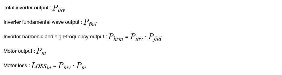
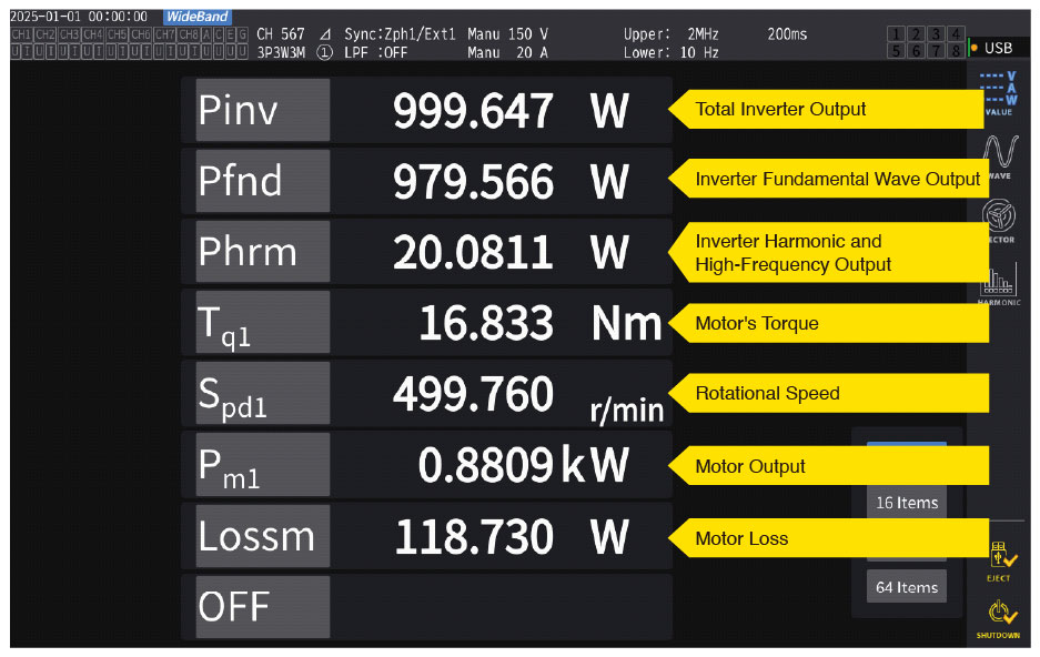
Measurement of fundamental wave output and motor output
The PW8001 - Power Efficiency and Loss Measurement
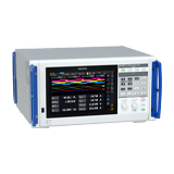
The Hioki PW8001 power analyzer (using the U7005 module) ensures precise efficiency and loss measurements for motor systems through three key capabilities.
First, it provides high accuracy across a wide frequency range, surpassing many high-end power analyzers. The high-end module U7005 attains a power accuracy of ±(0.02% of reading + 0.03% of range) for DC, ±(0.01% of reading + 0.02% of range) at 50/60 Hz, and ±(0.15% of reading + 0.05% of range) at 50 kHz, covering frequencies from DC to 5 MHz. This high accuracy across a broad frequency range ensures reliable measurement of the inverter's three-phase AC output, enabling precise calculation of motor output and efficiency.
Second, the PW8001’s synergy with Hioki’s in-house current sensors enhances measurement reliability. Hioki can quote a combined accuracy specification for the analyzer and sensors—a feature often overlooked by other brands.
Finally, the PW8001’s automatic phase correction compensates for phase shifts in real time, achieving a phase accuracy close to ±0.2° at 50 kHz. By simply plugging in the sensors, the analyzer automatically recognizes the sensors and adjusts for their frequency response, ensuring accurate measurements even at low power factors (where phase errors are typically high).
These features make the PW8001 ideal for creating accurate efficiency and loss maps in motor systems.
Separating losses: copper and iron losses
Improving motor and inverter designs requires identifying inefficiencies by separating copper and iron losses. Copper losses result from the winding resistance (Pc = I²R), while iron losses are caused by eddy currents and hysteresis inside the core, both of which are influenced by magnetic field strength and frequency.
By using the PW8001 to separate losses and create loss maps based on operating conditions (e.g., current and torque axes for copper losses, speed and torque for iron losses), engineers can optimize components such as winding materials or core design to increase overall efficiency.
Calculation of copper losses
Copper losses in a motor occur due to the resistance of the coil windings when current flows through them. Therefore, by measuring the winding resistance of the motor in advance, the copper losses can be calculated using the current (Irms) measured by the power analyzer.
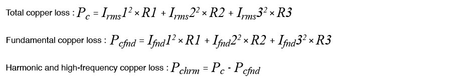
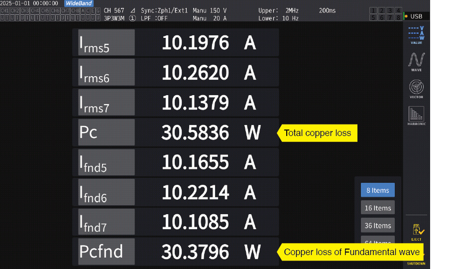
The power analyzer also measures the current of the fundamental wave (Ifnd), allowing you to calculate not only the total copper loss (Pc) but also the copper loss of the fundamental wave (Pcfnd). If the winding resistances of each phase of the motor are R1, R2, and R3, respectively, the copper losses can be calculated using the following equations. Additionally, the difference between Pc and Pcfnd represents the copper loss due to harmonic and high-frequency components (Pchrm).
The Hioki power analyzer PW8001 features a "User Defined Function (UDF)" capability, which allows you to define equations so that copper losses can be calculated alongside the measured values.
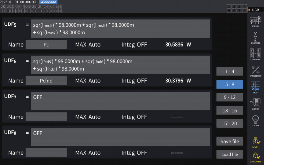
Example of User Defined Function (UDF) settings
Total copper loss : Pc and copper loss of fundamental wave: Pcfnd
In addition to a power analyzer, as mentioned above, the resistance of the winding must also be measured in order to calculate the copper loss. For this measurement, Hioki recommends the resistance meter RM3548. Despite being portable, its specifications rival R&D models at 0.02% accuracy and 0.1 Ω resolution. Furthermore, the current it applies to the motor to measure resistance can be set to a maximum of 1 A, enabling it to measure resistance of the MΩ order, necessary for large modern motors. Overall, the RM3548 is a versatile and high-performance unit for R&D engineers.
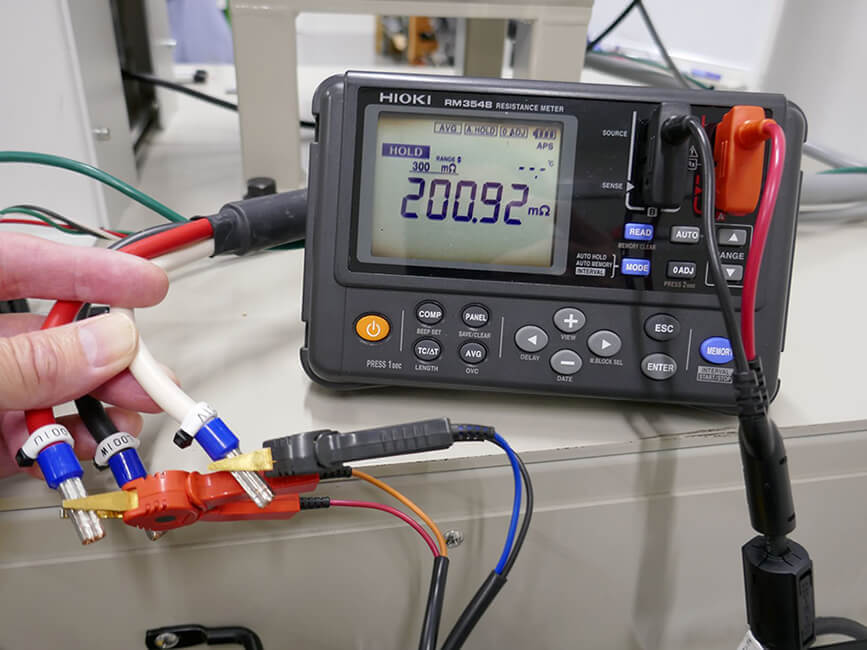 Measurement of motor winding resistance using the Resistance Meter RM3548
Calculation of iron losses
Iron losses can be determined from the outputs and losses calculated so far.

The mechanical losses are included here, but it is difficult to separately measure them, and since their proportion is generally small, they are included in the iron losses in this document.
Creating efficiency and loss maps
Efficiency and loss maps are essential tools for R&D engineers because observing the effects of operating conditions such as torque and speed on copper and iron losses helps inform design improvements.
However, efficiency inevitably varies as these conditions influence copper losses through current and iron losses through both frequency and current via magnetic fields. This variation in efficiency with respect to speed and torque may be adequate for motors with limited operating ranges but insufficient for applications such as EVs where a wide range of speeds and torques is required for regular operation.
Engineers can use the PW8001 power analyzer (characterized by high accuracy and harmonic analysis capabilities) to create efficiency and loss maps (total, copper, and iron losses), aiding in better decisions for improving inverter and motor design.
Example of efficiency map creation
Using obtained data from the PW8001, Hioki engineers created various efficiency and loss maps using MATLAB*. Below is one of the maps that were generated.
- *:MATLAB is a software product by MathWorks.
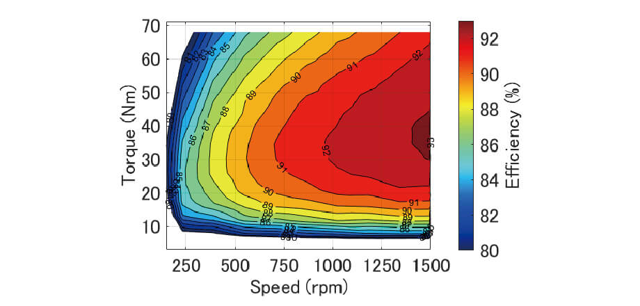
Efficiency map
Challenges and solutions for high-precision efficiency maps
As we have discussed earlier, motor efficiency can be calculated from the inverter output and motor output. However, accurately measuring motor efficiency is challenging due to the following reasons.
- The inverter output is PWM modulated, which includes switching frequencies and their harmonic components, requiring the measurement of broadband power.
- The harmonic power of the inverter has a low power factor, making it difficult to accurately measure harmonic power if the phase error of the measuring instrument is significant.
- Motors operate over a wide range of rotational speeds, from low to high, necessitating high-precision measurements across the entire operating range.
As mentioned above, the PW8001 covers a wide frequency range from DC to 5 MHz and can measure with a basic accuracy of 0.03%. It also supports high-accuracy measurement of large currents with precise current sensors. Furthermore, its current sensor phase correction function high accuracy even at low power factors.
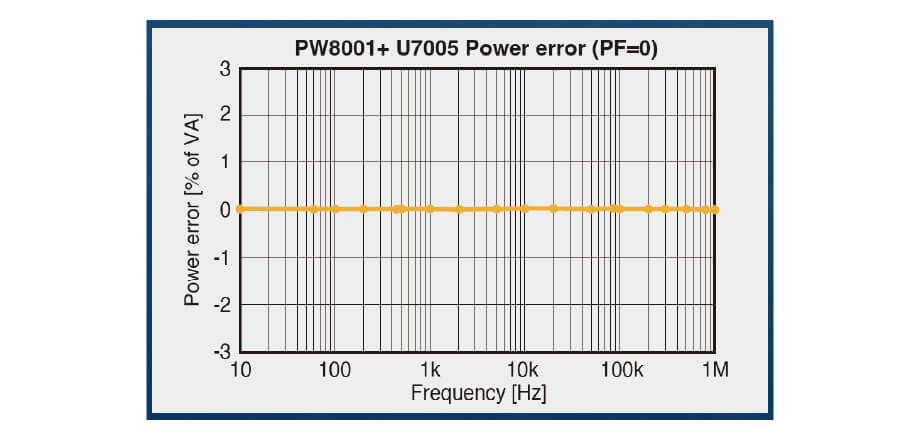
Frequency characteristics of the PW8001 at a power factor of 0
Conclusion
In this application note, we have guided readers through the measurement of a PWM-driven motor, analyzing power efficiency and loss, separating losses into copper and iron components, creating efficiency and loss maps, and addressing challenges with Hioki's PW8001 and in-house current sensors. We have translated theoretical knowledge of power efficiency and loss types into practical strategies for R&D design improvements.
For more information on how the PW8001's high accuracy and analysis capabilities can elevate your R&D, please feel free to visit the PW8001's product page or contact a Hioki expert using our contact form.