Temperature Correction Using a Radiant Temperature Sensor for Measurement of the Resistance of Flat Enameled Wire
Issues
Resistance values vary with the temperature of the device under test (DUT). Resistance meters have a terminal for connecting a temperature sensor, as well as functionality for converting measured resistance values at the current temperature to resistance values at standard temperature (temperature correction functionality). This functionality makes it possible to measure resistance without the effects of temperature variations. When measuring a DUT that has acclimated to the ambient temperature at a site like a factory, the DUT’s temperature is assumed to be the same as the indoor temperature for the purpose of temperature correction. When there’s a difference between the DUT’s temperature and the indoor temperature, or when the temperature of individual DUTs varies, temperature is corrected using non-contact measurement with a radiant temperature sensor as part of automatic testing processes. However, radiant temperature sensors do not yield accurate temperature readings when measuring DUTs made of lustrous, low-emissivity materials. In addition, the temperature of individual DUTs varies on stator manufacturing lines, which test winding resistance before any time has elapsed since the upstream process was completed. Temperature correction using the actual temperature of DUTs has long been a challenge in resistance measurement.
Solution
An object’s emissivity depends on the nature of its surface and shape. Consequently, in some cases it is desirable to determine emissivity by taking an emissivity value based on physical constants and comparing the result with the temperature value from a contact-type temperature sensor. Keyence’s FT series of radiant temperature sensors provides functionality for determining emissivity by inputting the temperature value from a contact-type temperature sensor to its amplifier for use as a calibration value.
[Precautions]
• Use a thermocouple with a thin wire that reacts quickly as the contact-type temperature sensor.
• Ensure sufficient contact between the thermocouple and the object being measured.
• Calibrate the instrument at least 20°C higher than room temperature. (Emissivity can be determined more precisely at high temperatures.)
• Use a logger that can accommodate temperature measurement using thermocouples without being affected by noise from the heat source.(Some loggers exhibit temperature value variability due to the effects of noise.)
• If using a chamber, take steps to block airflow and implement a thermal barrier to isolate the DUT from the heat source.
• Position the thermocouple and radiant temperature sensor close to each other, but not so close that they could come into contact.
• Use the value once the thermocouple’s temperature measurement stabilizes.
(Since the temperature at different locations will be measured, it’s necessary for the object under measurement to be at uniform temperature.)
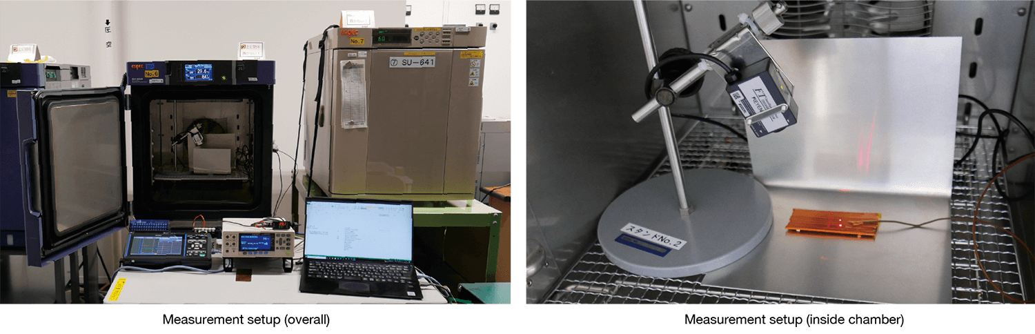
[Measurement method]
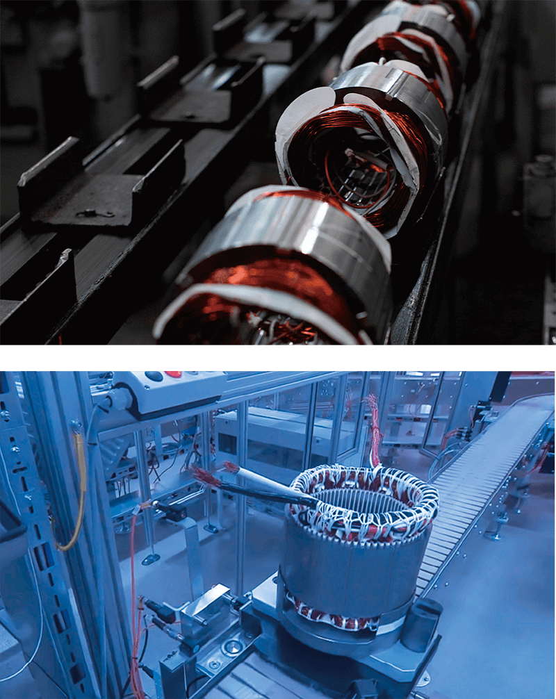
• Use flat enameled wire as the DUT.
• Affix a T-type thermocouple to the DUT and place the sensor head (FT-H20) close to it.
• Convert the 4 to 20 mA output from the sensor to 1 to 5 V with a 250 Ω resistor.
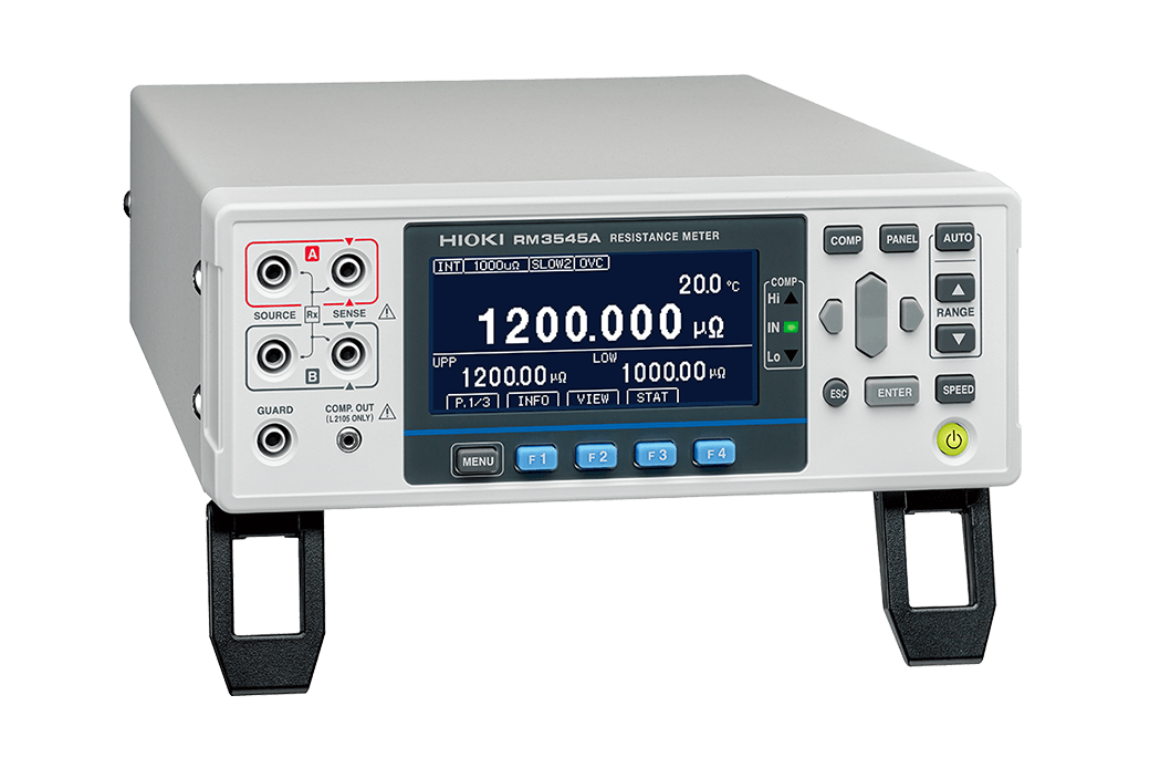
• Input the 1 to 5 V to the RESISTANCE METER RM3545A.
• Connect the T-type thermocouple to the LR8450 MEMORY HiLOGGER.
• Surround the DUT with aluminum or Bakelite to block airflow and create a thermal barrier between it and the heat source.
• Set the chamber to 45°C and 50% RH and activate it.
Once the temperature stabilizes, input the thermocouple’s temperature value to the sensor’s amplifier and determine the emissivity.
• Connect the RM3545A and LR8450 to a PC.
• Using a program created with Sequence Maker*, read both temperature values at the same time while varying the chamber temperature.
* “Sequence Maker” is an Excel add-in that provides integrated control of measuring instruments. It supports USB, RS-232C, LAN, and GP-IB as communications interfaces. It also supports VISA, a model-agnostic communications driver for instruments. Since it can automatically search for and connect to instruments that are connected to a PC, you can implement the desired control by noting the control commands you wish to execute in order in the Excel file.
-
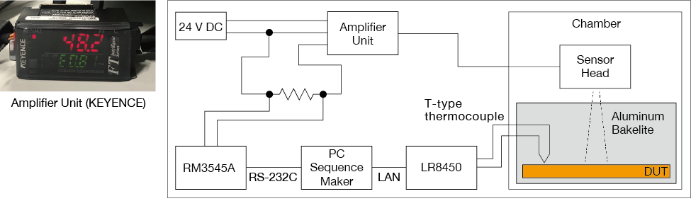
Measurement circuit diagram
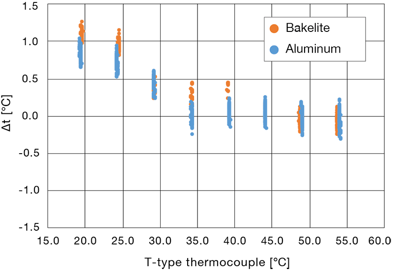
Measurement data
Right figure provides a graph of Δt (the value obtained by subtracting the thermocouple temperature from the radiant temperature sensor temperature) based on the T-type thermocouple.
• At and above 35°C, Δt is within ±0.5°C.
• The increased error at and below 30°C is likely due to the reduced amount of radiation from the DUT.
• The DUT was enclosed in Bakelite and aluminum to block airflow in the chamber and to form a thermal barrier between the DUT and the heat source.
• The aluminum, which is characterized by lower radiation, was more effective as a thermal barrier.
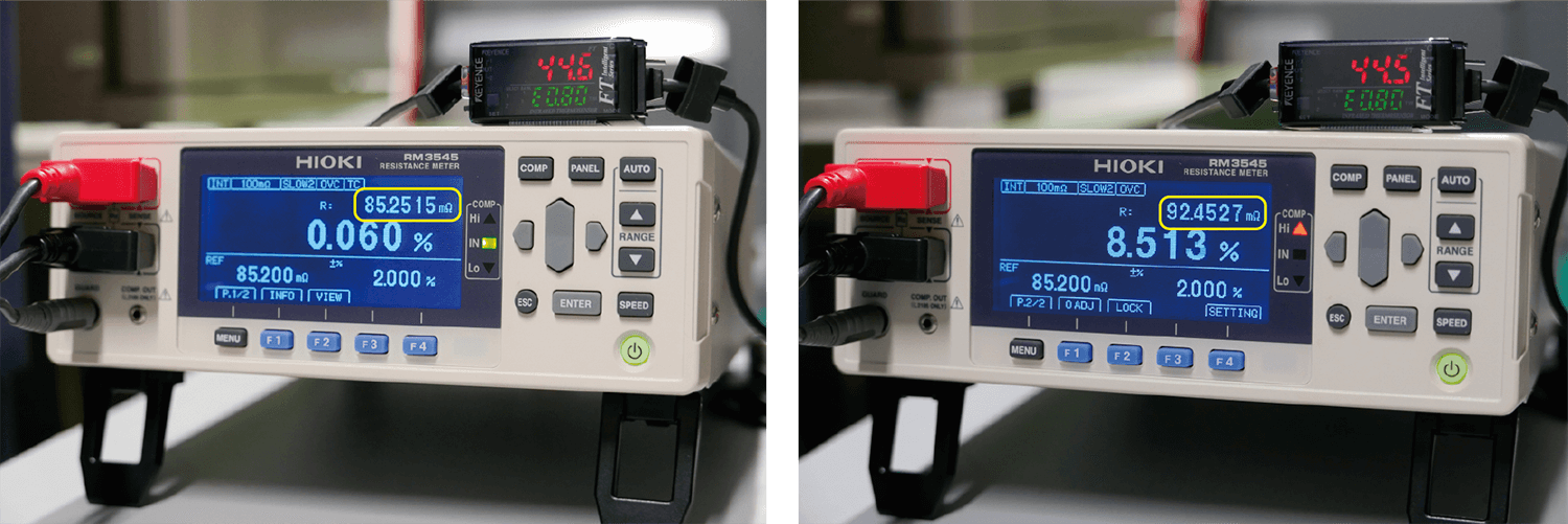
Measurement data (temperature correction function)
• A coil with a reference value of 85.2 mΩ at 23°C was measured using the RESISTANCE METER RM3545A after performing temperature correction with a radiant temperature sensor.
• At a coil temperature of approximately 44.5°C, this process yielded a resistance value of 85.2515 mΩ after conversion to 23°C (left figure).
• Without temperature correction, the reading was 92.4527 mΩ (right figure).
• These results demonstrate the extent of the effect of temperature on resistance values as well as the importance of temperature correction in resistance measurement.