Testing varnish impregnation state in a motor with an LCR meter
After their coils are wound, motors undergo a varnish impregnation treatment. There are two types of varnish impregnation treatments: trickle impregnation, in which the coil is immersed in a tank of varnish (which serves as an insulating material), and vacuum impregnation, in which varnish is injected after the coil is subjected to a vacuum. By reinforcing the insulating function of the inside of the coil and the insulating paper while filling in gaps inside the coil, varnish impregnation keeps out moisture and dust, which can lead to degradation of the insulation. Differences in the varnish impregnation state of motors can be clearly ascertained by measuring tan δ at a low frequency with an LCR meter.
Checking the impregnation state
Generally, a dielectric loss tangent meter (tan delta meter) is used to test the varnish impregnation state of motors. The dielectric loss tangent (tan δ) serves as a numerical indicator of the condition of electrical insulating materials. When an AC voltage is applied to a motor’s insulator (between the coil and ground), dielectric loss occurs. The dielectric loss tangent expresses the extent of this loss. Dielectric loss tangent meters make measurements by applying a comparatively high voltage of 50 Hz or 60 Hz. The dielectric loss , or the Loss tangent can be expressed as follows: tan δ = 1/2πfCRp. In this formula, tan δ increases as the frequency f decreases. In other words, the difference between two tan δ values measured at a low frequency will be greater than the corresponding values obtained by performing measurements at 50 Hz/60 Hz, making it easier to discern differences in the impregnation state. LCR meters can measure tan δ at frequencies that are lower than 50 Hz/60 Hz.
(The figure below shows the equivalent circuit for an insulator and vectors when an AC voltage is applied )
How to test
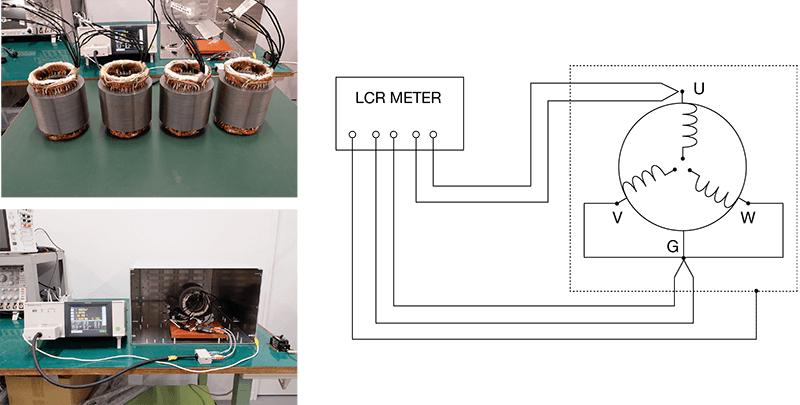
■ Test samples (four stator samples): Defective (insufficient varnish volume) and non-defective parts prepared with trickle impregnation, and defective (insufficient vacuum strength) and non-defective parts prepared with vacuum impregnation.
■ Measurement method: The dielectric loss, or Loss tangent (tan δ) was measured between the coil and core using an LCR meter. Since this involves measuring an insulator, a shield box was prepared, and measurements were made after connecting the shield box to the LCR meter’s shield terminal.
■ Measurement frequencies: 1 Hz, 5 Hz, 10 Hz, 20 Hz, 50 Hz, 60 Hz
[The figure below shows an example of measurement circuit (U-VWG)]
Measurement data
Different values were obtained for the defective and non-defective parts at all measurement frequencies. The difference between defective and non-defective parts was more pronounced at lower measurement frequencies.
The following graphs show f-tanδ characteristics of defective/non-defective samples.
(Left: trickle impregnation, right: vacuum impregnation)


