News Mar. 07, 2023
6 Solutions for Testing of Components/Devices in Operation
1. Loss Analysis of Reactors while in Operation
Why does the loss analysis of inductors matter?
It is important to understand the amount of energy lost when it comes to the analysis of reactors because this can affect the range of an electric vehicle (EV). This is an area of particular concern to both current and potential owners of EVs, as range anxiety is a major factor in their buying decision. To increase the range of an EV, the efficiency of the system as a whole needs to be improved. A large amount of the loss in power conversion circuits is caused by the use of inductors, or reactors. Therefore, to get the best out of the system, it is necessary to calculate the losses from the inductors with precision.
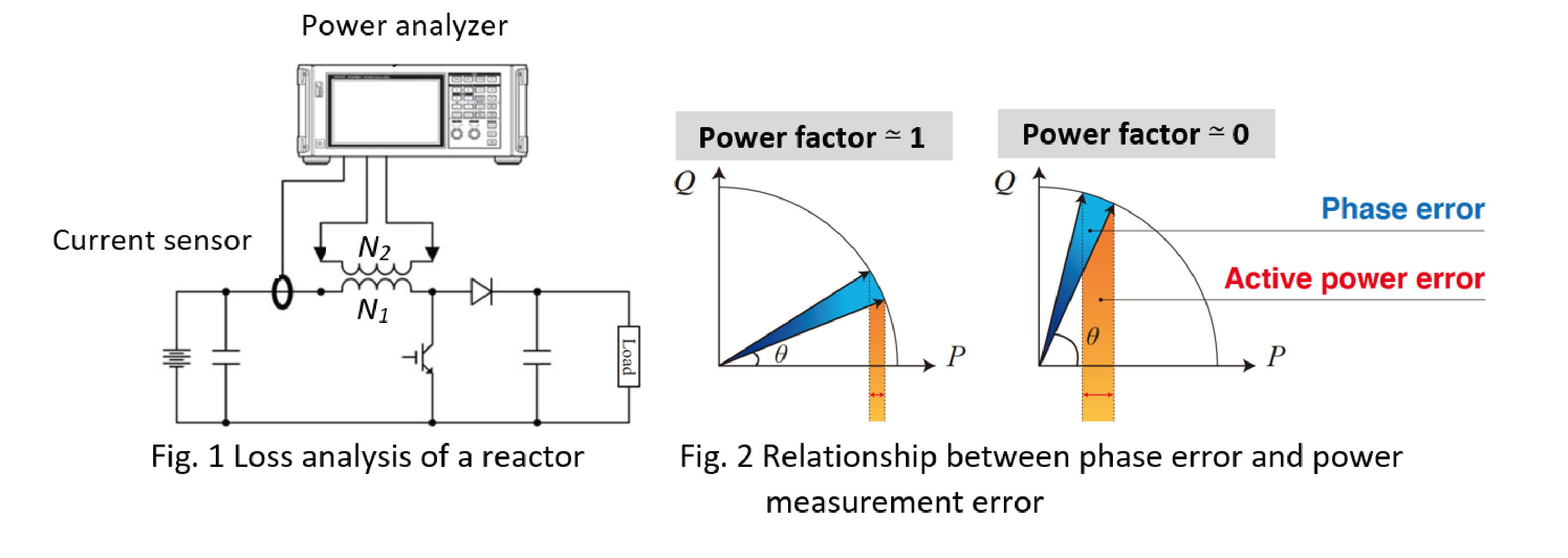
Loss analysis of the reactor is performed by applying high-frequency current signals to the reactor and measuring with a power analyzer the reactor loss as well as core loss using a detection winding coil that can identify core magnetic flux (Fig. 1). This, however, is not an easy job since measured signals are distorted by high frequency switching over the inductor, meaning signals with a broad range of frequencies need to be analyzed, and the measurement instrument’s phase error, or current sensor’s in most cases, has a significant effect on error in loss measurement due to measurement at low power factor (Fig. 2).
Solution
Measurement systems for the loss analysis of reactors are required to be at least two times faster and have a wider frequency range than target signals, including harmonics. In addition, they must have excellent A/D resolution, moreover the phase error of the current sensors needs to be reasonably corrected in a broad frequency range.
The PW8001 power analyzer offers industry-leading accurate power analysis with 15 MS/s data sampling, 18-bit A/D resolution, and a frequency range of DC, 0.1 Hz to 5 MHz. The current sensor’s phase error is automatically corrected just after the connection is established (Plug and Play feature).
2. Inverter and Motor Analysis in Areas where Multi Phasing Technology is Actively Studied
Research on multiphase control of motors has been active
To create a sustainable society, numerous endeavors to cut down greenhouse gas emissions are being undertaken. One of these is the switch to electric power for automobiles and aircraft. This increased demand for motors with higher output and dependability for the power supply has led to the study of multiphase control of motors in order to guarantee that even if a section of the inverter fails, the motor will not cease operation. Furthermore, research and development are being conducted to enhance motor output while simultaneously reducing current and voltage with multi-phasing and several controls.
Solution
The PW8001 by HIOKI can measure up to eight channels simultaneously, allowing assessment of the power input/output and performance of a six-phase motor system with a single instrument. It boasts high precision, reliability, a wide frequency range, and repeatability when measuring inverter input/output power.
- Basic accuracy ±0.03 %, DC accuracy ±0.05 %, 50 kHz accuracy 0.2 %
- Frequency flatness: band where amplitude falls within ±0.1 % range: 300 kHz
- Frequency flatness: band where phase falls within ±0.1° range: 500 kHz

In addition, the PW8001 is equipped with abundant trigger functions to reliably capture transient waveforms and analyze their behavior in anticipation of emergency situations.
Furthermore, it has an abundance of trigger functions to effectively capture transient waveforms and analyze their behavior in the event of an emergency.
3. Real-time Torque Correction
Low motor efficiency? What does it have an impact on?
Electric vehicles are powered by energy stored in batteries. The total efficiency of the system is determined by the individual effectiveness of each component. If the motor has 87 % efficiency, the inverter 98 %, and the rest of the elements 90 %, the total efficiency is 77 %. A low motor efficiency has a major effect on the whole efficiency, generating thermal issues and a limited driving range after a charge. To increase the total system efficiency, it is essential to evaluate the motor efficiency precisely.
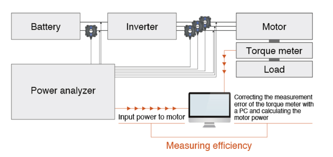
Motor efficiency is calculated from the power output and input of the motor. The output power is determined by the output of a rotary encoder and a torque meter. A precision power analyzer carries out the analysis of motor. However, the motor analysis feature is not utilized as it does not typically have a function to make up for mistakes from the torque meter, like linearity and friction errors. Error compensation is performed with a PC and it calculates motor power after compensation (Fig.1). This results in asynchronous timing of motor input and output measurements, leading to variation in efficiency and loss.
Solution
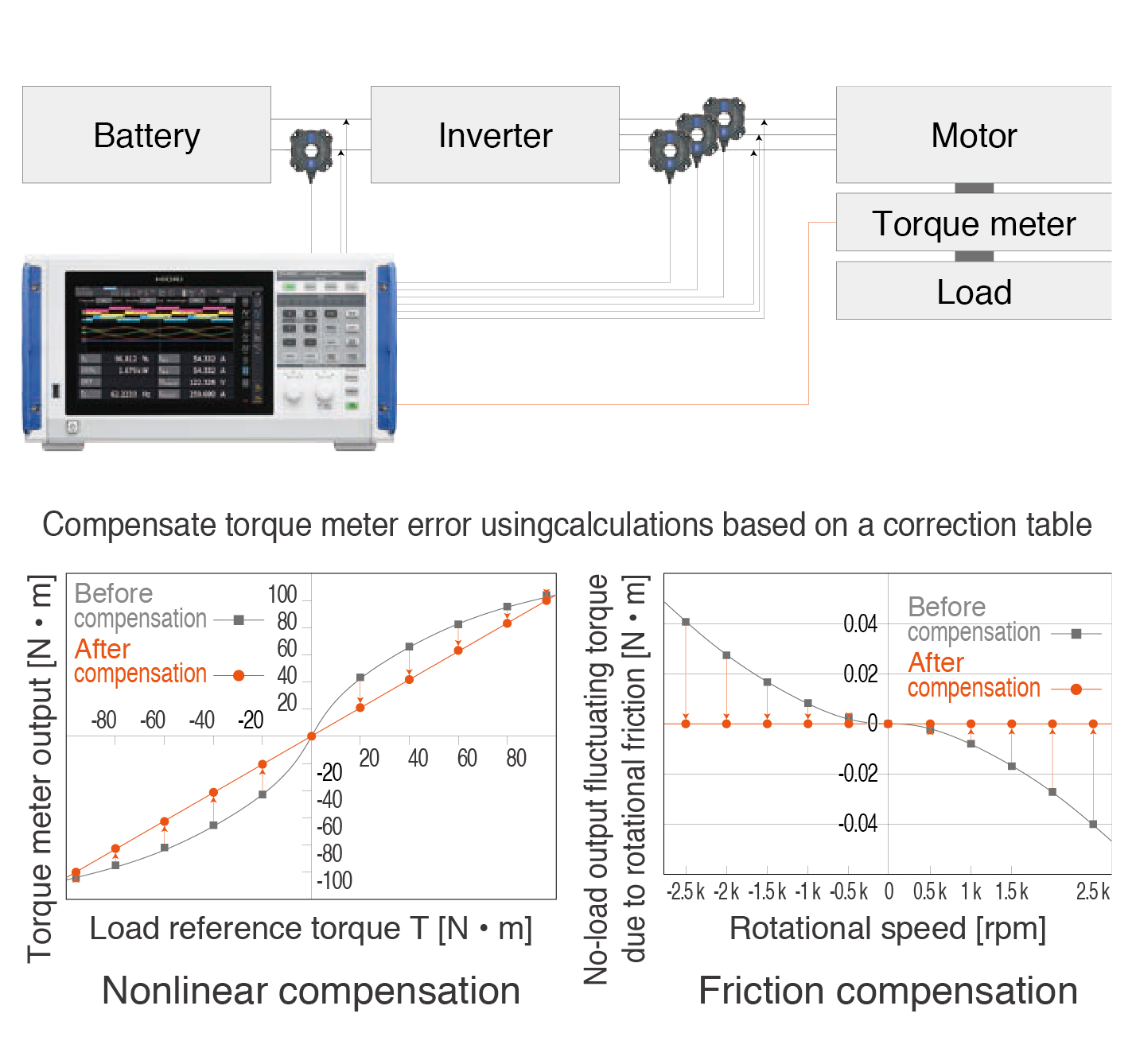
A real-time torque compensation resolves the issue of variation in efficiency and loss caused by the asynchronous timing. The power analyzer is required to have such a feature and a table for correction should be made of calibration results of the torque meter, leading to accurate motor analysis.
The PW8001 power analyzer has a real-time torque correction feature that enables correcting both linearity and friction errors across 11 points. This produces more precise torque measurement and motor analysis (Fig.2).
4. Stable Logging - Even at High Voltages and Frequencies. Minimize the Effects of Noise
Temperature affectation in electronic components
Temperature affects the performance of electrical components in many ways. As temperature increases, electrical components may become less reliable, have shorter lifespans, and reduce power output. It is significant to measure the temperature of electronic components while they are working to make sure that they are within the anticipated temperature range.
Accurately logging temperature requires the use of contact sensors such as RTDs or thermocouples. It is complicated to measure the temperature of the parts in use since they are powered by high voltages and frequencies that produce electrical noise. This noise will affect the stability and accuracy of the temperature readings taken.
Solution
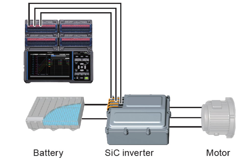
The LR8450 reduces the effects of noise to deliver stable logging, even at high voltages and frequencies. Following image illustrates an arrangement for measuring the temperature of the motor drive inverter as an example of measurements that demonstrate the improved noise resistance of the LR8450.
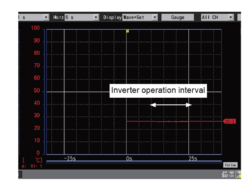
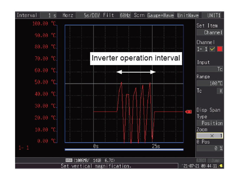
The results indicate that previous model exhibits variability in the measured values caused by high frequency noise starting immediately after the inverter starts operating and lasting until it stops. By contrast, the LR8450 exhibits a considerable enhancement in its noise resistance, with minimal effect on the measured values, even when the inverter starts operating.
5. Evaluate the Efficiency of Wireless Power Transfer (WPT) Systems
Challenges in Measuring the Efficiency of Wireless Power Transfer
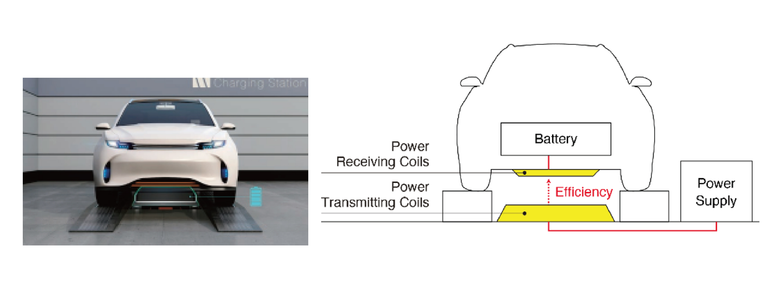
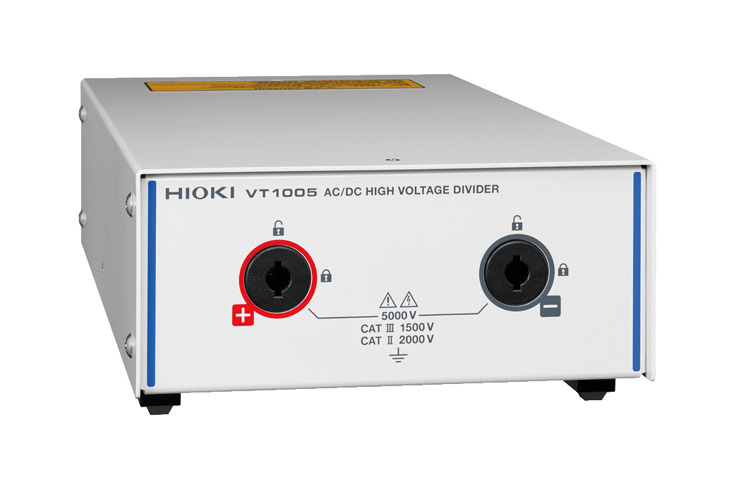
The amount of energy a WPT system transmits to the battery is directly linked to the charging rate. Just a small portion of power loss in the wireless transmission process results in too much heat, which can have serious consequences on the battery system; it could reduce its lifespan and even cause a fire. To reduce power loss, the output voltage of the system has been raised to 3000 V. The WPT system utilizes two coils and works at a frequency of 85 kHz for power transmission. This makes it quite challenging to measure the efficiency accurately as the phase approaches 90 deg. which leads to a low power factor. This error increases further as the frequency of the target signals rises. This makes it even more difficult to measure the harmonics of the switching frequency. Standard power analyzers cannot directly measure such high voltages. Even if it is possible to measure these high voltage levels with differential probes or voltage dividers, there is still a problem to be solved: correctly determining phase at both high switching rates and low power factors.
Solution
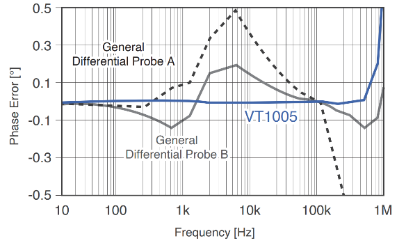
The VT1005 is capable of measuring up to 5000 volts for power measurements and has a frequency range from 0 to 4MHz (Fig.1). In comparison to conventional differential probes and high-voltage dividers, the VT1005 boasts a very flat frequency response in both phase and gain characteristics. This makes the VT1005 an ideal option to be used alongside the PW8001 to accurately measure the power conversion efficacy of low power factor WPT systems.
6. Overwhelming Usability
Have you ever encountered any of these issues?
- Having to prepare a distinct energy source for the sensor can be inconvenient.
- It is also time-consuming to reset the sensor rate each time the sensor is substituted.
- The phase correction function is convenient, but it is troublesome to input the data manually while reading the instruction manual.
Solution
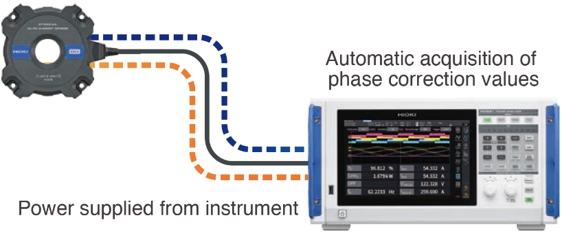
To eradicate any issues, HIOKI's PW8001 and its compatible current sensor with the Auto Interface are the go-to solution. The PW8001 not only provides power for the current sensor but is also capable of recognizing the model and serial number. Additionally, it adjusts the scaling ratio for each of the current sensors used accordingly. Moreover, the PW8001 recognizes the phase characteristics of each current sensor with a precision of 0.001° and performs phase correction as well. All these features enable the instrument to reach its full potential without any complicated configuration process.
Furthermore, for attaining accurate results and ensuring data credibility, it is essential to keep a record of the used equipment (model and serial number).
With the new Auto Interface, all sensor information as well as wattmeter information can be acquired and managed on the system side.
Download the full whitepaper from Hioki