Measurement Guide of the motor parameters Ld and Lq
Advanced sine-wave control is employed in electric vehicle motors to efficiently manage motor speed across a wide range, from low to high speeds. This technology is essential for balancing fuel efficiency and driving performance.
This application note explains the measurement methods for motor parameters critical to electric motors' vector control (field-oriented control). These parameters are used not only in electric vehicle motors but also in permanent magnet synchronous motors (PMSMs), which are widely used as high-efficiency motors for industrial use. Utilizing Hioki's power analyzer and PC software for motor parameter measurement, parameters dependent on drive conditions can be accurately and efficiently collected.
Differences between q-axis and d-axis inductance
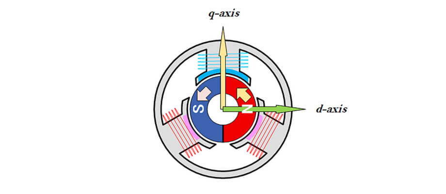
The relationship between the motor rotor (rotor), d-axis, and q-axis
What are Ld and Lq parameters?
The motor parameters Ld and Lq represent the inductances linked to the d-axis and q-axis, respectively, which are perpendicular to each other within the motor's rotating magnetic field. These parameters are essential for implementing vector control in permanent magnet synchronous motors (PMSM) and synchronous reluctance motors (SynRM).
- d-axis inductance (Ld): The d-axis aligns with the magnetic field direction of the permanent magnet. Ld represents the inductance on the axis passing through the center of the magnetic poles.
- q-axis inductance (Lq): The q-axis is perpendicular to the d-axis. Lq represents the inductance along this axis which contributes to torque generation.
The basic difference between Ld and Lq arises from the characteristics of the permanent magnets, their arrangement, and the overall design of the motor. In addition, Ld and Lq also decreases as the drive current increases. For those developing PMSMs and their control systems, it is essential to comprehend these current-dependent characteristics of Ld and Lq in order to create precise and effective motor control strategies.
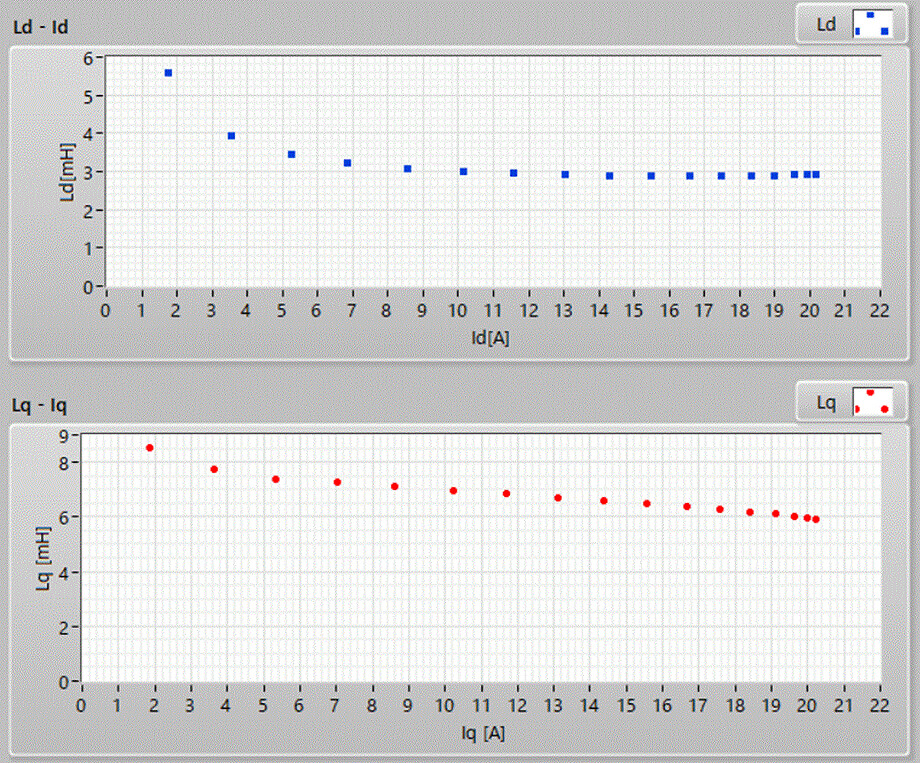
Example of current-dependent d-axis and q-axis inductance
Why power analyzers are ideal for measuring Ld and Lq
Power analyzers have high-accuracy sensing and computational capabilities, making them more efficient than other measurement methods for determining Ld and Lq. They can precisely sense the magnitude and phase of drive currents and calculate parameters using rotor angle data.
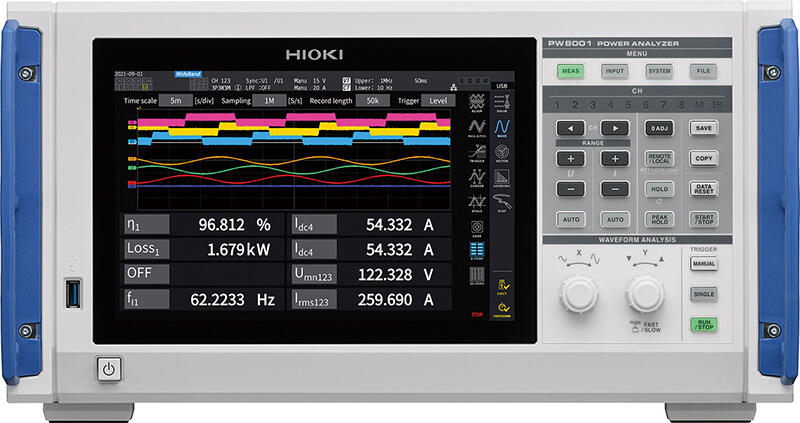
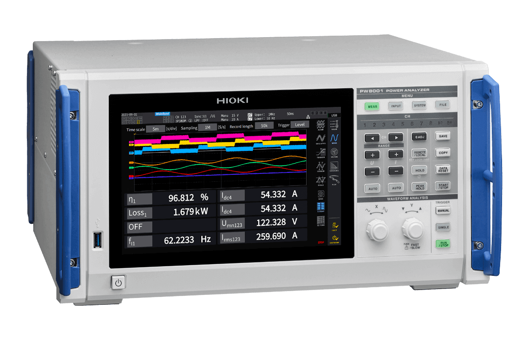
POWER ANALYZER PW8001
When analyzing motor parameters Ld and Lq, it is necessary to accurately sense the magnitude and phase of the drive current and calculate the parameters through computation. The measuring tool must meet two key requirements:
- High measurement accuracy for amplitude and phase of voltage and current.
- The ability to detect the rotor's rotational angle and calculate the current based on the d-axis.
To measure Ld and Lq, it is necessary to accurately measure the phase and RMS value of the fundamental component based on the waveform of the voltage and the current generated by PWM control. This requires not a waveform recorder like an oscilloscope, but a dedicated device with high-resolution, high-accuracy waveform processing capabilities and dedicated harmonic analysis functions, that is, a power analyzer.
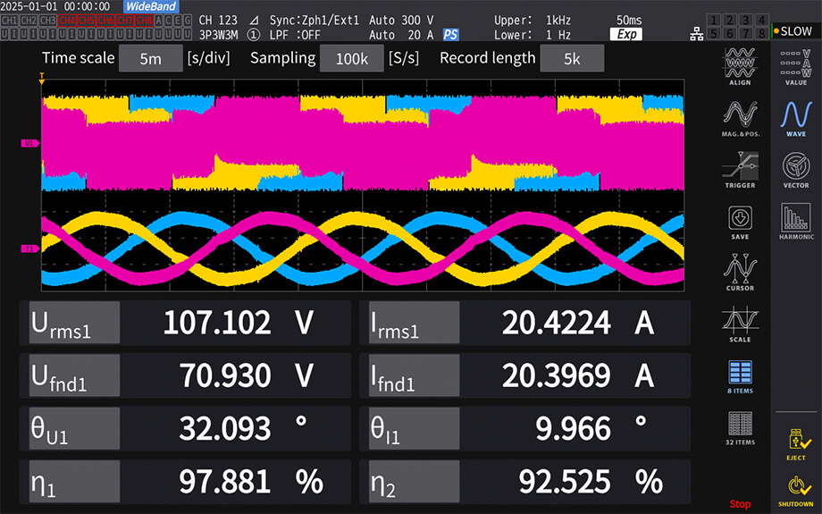
POWER ANALYZER PW8001 enables voltage and current measurements of PWM inverter drive motors and accurate measurement of motor power efficiency
Control engineers apply the measurement results of Ld and Lq to control programs and verify whether the values can be used to improve the motor's characteristics and efficiency. In this regard, power analyzers allow simultaneous verification of efficiency measurement (which vary based on motor speed and torque) as well as the Ld and Lq parameter measurements. A high-precision power analyzer enables comprehensive evaluation by acquiring data just once.
Measurement of Ld and Lq
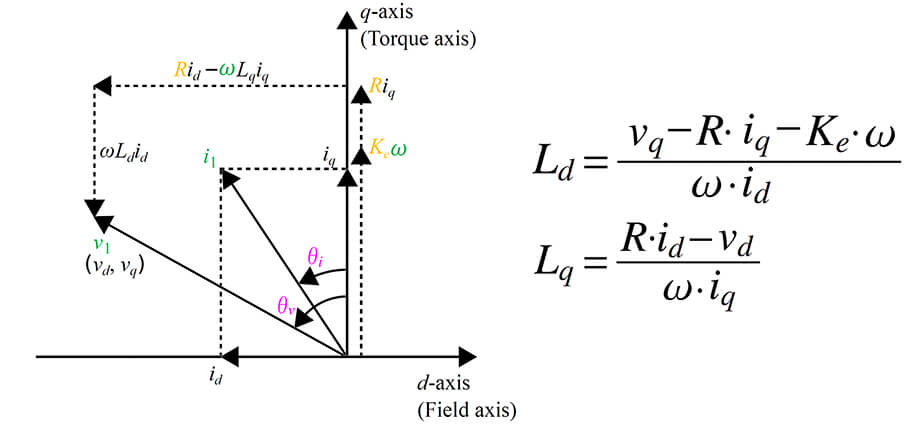
Ld and Lq as inductances calculated from the voltage and current of the d-axis and q-axis
Before acquiring Ld and Lq data, it is necessary to measure two constants (R and Ke) required for their calculation. The following outlines the actual measurement procedure.
1. Measure armature resistance (R)
Use a high-accuracy resistance meter, such as Hioki's RM3548, to measure the motor's three-phase winding resistance. Average these values to calculate armature resistance R.
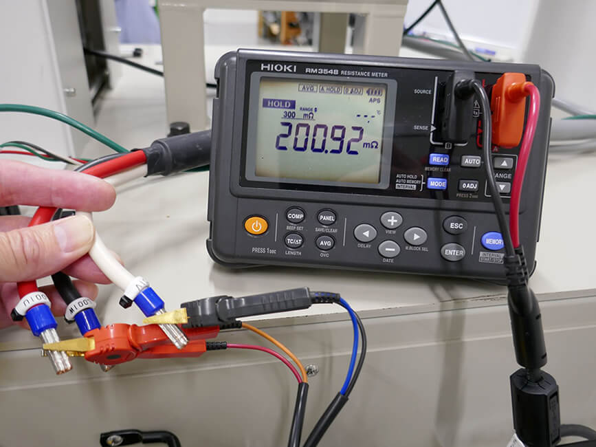
Measurement of motor armature resistance using Resistance Meter RM3548
2. Connect the equipment
Connect the current sensor and voltage cables to the 3-phase motor drive wires to sense motor drive current, voltage, and rotor angle. Since phase zero-adjustment is required, drive the device under test (DUT) motor using a load motor to measure the motor-induced voltage.
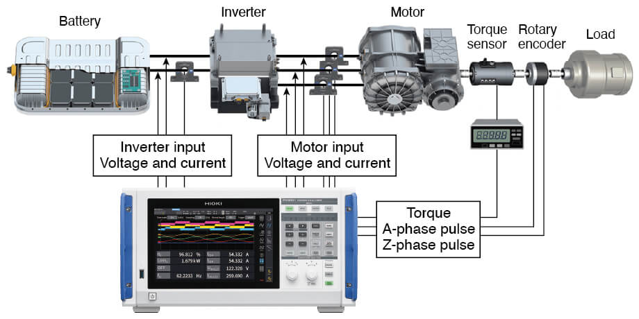
Configuration of the motor evaluation system
3. Perform phase zero-adjustment and measure Ke constant
Follow guided setup steps in the PC software for accurate phase alignment and induced voltage constant (Ke) measurement.
PW8001 Ld, Lq Analyzer
- Phase zero-adjustment: real-time graphing allows intuitive confirmation of phase alignment, with a 0-degree plot indicating successful adjustment.
- Induced voltage constant (Ke) measurement: displays real-time stability of Ke values; supports the accurate determination of constant Ke parameter for Ld and Lq calculations.
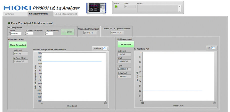
Phase zero-adjustment and Ke measurement screen of the PW8001 Ld, Lq Analyzer
4. Measure Ld and Lq
The acquisition of measurement data and the calculation of motor parameters are performed entirely automatically when using Hioki's PW8001 Ld, Lq Analyzer software. For further insights, utilize the PC software for real-time graphing and analysis of Ld and Lq values, including X-Y graphs.
- Real-time plotting of Ld and Lq
- X-Y graphs of Ld-Id and Lq-Iq
- Real-time plotting of basic power data and up to six motor power parameters
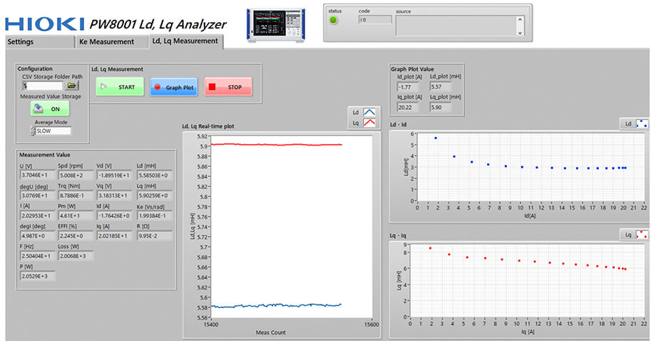
Real-time plot graph of Ld and Lq
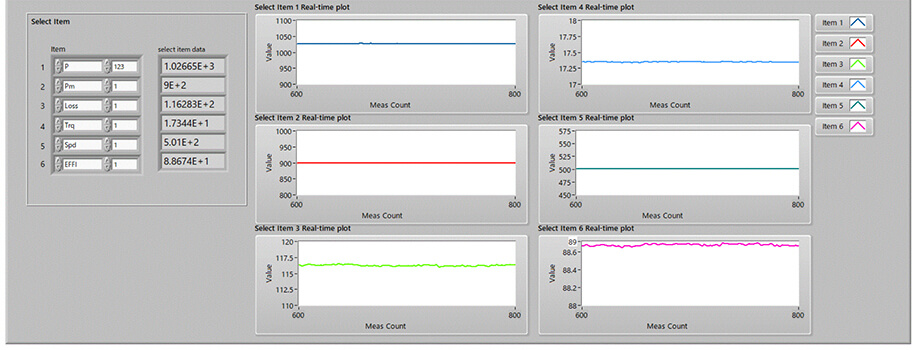
Real-time plot of motor power and efficiency
The Power Analyzer PW8001 is ideal for acquiring Ld and Lq data for motors.
Conclusion
This article addressed the following:
- Why accurate Ld and Lq values are critical for motor control
- How to measure Ld and Lq
Advanced vector control for electric motors relies on identifying accurate Ld and Lq values under various conditions to validate performance improvements.
Download of software
Hioki's power analyzer, along with its intuitive software, not only ensures precise parameter measurements but also reduces evaluation effort and shortens development timelines.
Download the PW8001 Ld, Lq Analyzer software here.
To display the Ld and Lq parameters in real time on the power analyzer’s built-in screen, please download and use the UDF configuration file provided here.