Syntax |
Command |
*CLS |
Query |
|
|
Response |
|
|
Parameter |
|
|
Explanation |
Command |
Clears the content of the event registers (SESR, ESR0, ESR1, ESR2, ESR3). |
Query |
|
|
Example |
Command |
*CLS |
Query |
|
|
Response |
|
|
Note |
GPIB: The output queue is unaffected. |
Syntax |
Command |
*ESE <Mask value> |
Query |
*ESE? |
|
Response |
<Mask value> |
|
Parameter |
<Mask value> = 0 to 255 (NR1) |
|
Explanation |
Command |
Sets the mask pattern of SESER. |
Query |
Returns the mask pattern of SESER. |
|
Example |
Command |
*ESE 36 |
Query |
*ESE? |
|
Response |
*ESE 36
(when HEADER ON) |
|
Note |
|
Syntax |
Command |
|
Query |
*ESR? |
|
Response |
<Register value> |
|
Parameter |
<Register value> = 0 to 255 (NR1) |
|
Explanation |
Command |
|
Query |
Returns the register value of SESR, and clears the register. |
|
Example |
Command |
|
Query |
*ESR? |
|
Response |
32
|
|
Note |
Bit 6 and 1 are not used in the instrument. |
Syntax |
Command |
|
Query |
*IDN? |
|
Response |
<Maker Name>,0,< Model Name>,<Software Version> |
|
Parameter |
|
|
Explanation |
Command |
|
Query |
Returns the ID of the instrument. |
|
Example |
Command |
|
Query |
*IDN? |
|
Response |
HIOKI,IM3570,0,V1.00
|
|
Note |
|
Syntax |
Command |
*OPC |
Query |
|
|
Response |
|
|
Parameter |
|
|
Explanation |
Command |
Sets the OPC (bit 0) of the SESR (standard event status register) at the point in time that command processing finishes for the sent commands which are before the command. |
Query |
|
|
Example |
Command |
A;B;*OPC;C |
Query |
|
|
Response |
|
|
Note |
|
Syntax |
Command |
|
Query |
*OPC? |
|
Response |
|
|
Parameter |
|
|
Explanation |
Command |
|
Query |
Sends the response of ASCII 1 at the point in time that command processing finishes for the sent commands which are before the *OPC command. A header is not added to the response message. |
|
Example |
Command |
|
Query |
*OPC? |
|
Response |
1
|
|
Note |
|
Syntax |
Command |
*RST |
Query |
|
|
Response |
|
|
Parameter |
|
|
Explanation |
Command |
Initializes the instrument. |
Query |
|
|
Example |
Command |
*RST |
Query |
|
|
Response |
|
|
Note |
When the instrument is initialized, the current setting information is deleted and the instrument is restored to the initial state. |
Syntax |
Command |
*SRE <Mask value> |
Query |
*SRE? |
|
Response |
<Mask value> |
|
Parameter |
<Mask value> = 0 to 255 (NR1) |
|
Explanation |
Command |
Sets the mask pattern of SRER. |
Query |
Returns the mask pattern of SRER. |
|
Example |
Command |
*SRE 34 |
Query |
*SRE? |
|
Response |
*SRE 34
(when HEADER ON) |
|
Note |
|
Syntax |
Command |
|
Query |
*STB? |
|
Response |
<Register value> |
|
Parameter |
<Register value> = 0 to 255 (NR1) |
|
Explanation |
Command |
|
Query |
Returns the register value of STB. |
|
Example |
Command |
|
Query |
*STB? |
|
Response |
8
|
|
Note |
|
Syntax |
Command |
*TRG |
Query |
|
|
Response |
|
|
Parameter |
|
|
Explanation |
Command |
Performs sampling once when there is an external trigger. |
Query |
|
|
Example |
Command |
:TRIGger EXTernal;*TRG;:MEASure? |
Query |
|
|
Response |
|
|
Note |
An execution error occurs if this command is executed when there is an internal trigger. |
Syntax |
Command |
|
Query |
*TST? |
|
Response |
<Result> |
|
Parameter |
<Result> = 0 to 15 (NR1) |
|
Explanation |
Command |
|
Query |
Executes the following self tests and returns the result.
The tests take approximately 1 minute. Do not send commands or turn off the power of the instrument during the tests. A header is not added to the response message. |
|
Example |
Command |
|
Query |
*TST? |
|
Response |
5
|
|
Note |
If the result is other than 0, the instrument may have malfunctioned. |
Syntax |
Command |
*WAI |
Query |
|
|
Response |
|
|
Parameter |
|
|
Explanation |
Command |
Executes the command following *WAI after command processing is finished. |
Query |
|
|
Example |
Command |
A;B;*WAI;C
:FREQuency 120;:MEASure? In this case, it is not certain which frequency measurement value will be sent in response to the :MEASure? query.
:FREQuency 120;*WAI;:MEASure? In this case, the 120 Hz frequency measurement value is sent in response to the :MEASure? query. |
Query |
|
|
Response |
|
|
Note |
Unique commands other than the ":MEASure?" query use sequential commands. |
Syntax |
Command |
:AVERaging <OFF/ number of averaging times> |
Query |
:AVERaging? |
|
Response |
<OFF/ number of averaging times> |
|
Parameter |
<number of averaging times> = 1 to 256 (NR1) |
|
Explanation |
Command |
Sets the number of averaging times. OFF: Disables the averaging function. |
Query |
Returns the number of measurement averaging times. |
|
Example |
Command |
:AVERaging 32 |
Query |
:AVERaging? |
|
Response |
:AVERAGING 32
(when HEADER ON) |
|
Note |
Setting the number of averaging times to 1 automatically sets the averaging function to OFF. |
Syntax |
Command |
:BEEPer:JUDGment <OFF/IN/NG> |
Query |
:BEEPer:JUDGment? |
|
Response |
<OFF/IN/NG> |
|
Parameter |
|
|
Explanation |
Command |
Sets the beep sound for the judgment results of measurement values. OFF: No beep sound. |
Query |
Returns the setting of the beep sound for the judgment results of measurement values. |
|
Example |
Command |
:BEEPer:JUDGment NG |
Query |
:BEEPer:JUDGment? |
|
Response |
:BEEPER:JUDGMENT NG
(when HEADER ON) |
|
Note |
|
Syntax |
Command |
:BEEPer:KEY <ON/OFF> |
Query |
:BEEPer:KEY? |
|
Response |
<ON/OFF> |
|
Parameter |
|
|
Explanation |
Command |
Sets the beep sound for key operation. ON: A beep sound is emitted. |
Query |
Returns the setting of the beep sound for key operation. |
|
Example |
Command |
:BEEPer:KEY ON |
Query |
:BEEPer:KEY? |
|
Response |
:BEEPER:KEY ON
(when HEADER ON) |
|
Note |
|
Syntax |
Command |
:BIN <OFF/ON> |
Query |
:BIN? |
|
Response |
<OFF/ON> |
|
Parameter |
|
|
Explanation |
Command |
Sets the BIN measurement function. OFF: Disables the BIN function. |
Query |
Returns ON or OFF for the BIN measurement function. |
|
Example |
Command |
:BIN ON |
Query |
:BIN? |
|
Response |
:BIN ON
(when HEADER ON) |
|
Note |
Sending the :BIN ON command during comparator measurement automatically ends comparator measurement and starts BIN measurement. |
Syntax |
Command |
:BIN:FLIMit:ABSolute <BIN number>,<OFF/ lower value>,<OFF/ upper value> |
Query |
:BIN:FLIMit:ABSolute? <BIN number> |
|
Response |
<OFF/ lower value>, <OFF/ upper value> |
|
Parameter |
<BIN number> = 1 to 10 |
|
Explanation |
Command |
Sets the upper and lower limit values of the first parameter in absolute value mode of the specified BIN number. |
Query |
Returns the setting of the upper and lower limit values of the first parameter in absolute value mode of the specified BIN number. |
|
Example |
Command |
:BIN:FLIMit:ABSolute 1,0.234567E-03,1.234567 |
Query |
:BIN:FLIMit:ABSolute? 1 |
|
Response |
:BIN:FLIMIT:ABSOLUTE 0.234567E-03, 1.234567
(when HEADER ON) |
|
Note |
The instrument stores the upper and lower limit values for absolute mode and those for percentage (%) mode separately. |
Syntax |
Command |
:BIN:FLIMit:DEViation <BIN number>,<OFF/ lower value>,<OFF/ upper value> |
Query |
:BIN:FLIMit:DEViation? <BIN number> |
|
Response |
<OFF/ lower value>, <OFF/ upper value> |
|
Parameter |
<BIN number> = 1 to 10 |
|
Explanation |
Command |
Sets the upper and lower limit values of the first parameter in deviation percentage (Δ%) mode of the specified BIN number. |
Query |
Returns the setting of the upper and lower limit values of the first parameter in deviation percentage (Δ%) mode of the specified BIN number. |
|
Example |
Command |
:BIN:FLIMit:DEViation 1,-10.0,10.0 |
Query |
:BIN:FLIMit:DEViation? 1 |
|
Response |
:BIN:FLIMIT:DEVIATION -10.0,10.0
(when HEADER ON) |
|
Note |
The instrument stores the upper and lower limit values for absolute mode and those for deviation percentage (Δ%) mode separately. |
Syntax |
Command |
:BIN:FLIMit:MODE <ABSolute/PERcent/DEViation> |
Query |
:BIN:FLIMit:MODE? |
|
Response |
<ABSOLUTE/PERCENT/DEVIATION> |
|
Parameter |
|
|
Explanation |
Command |
Sets the mode of the first parameter. ABSolute: Sets the mode to absolute (ABS) mode. |
Query |
Returns the mode of the first parameter. |
|
Example |
Command |
:BIN:FLIMit:MODE PERcent |
Query |
:BIN:FLIMit:MODE? |
|
Response |
:BIN:FLIMIT:MODE PERCENT
(when HEADER ON) |
|
Note |
|
Syntax |
Command |
:BIN:FLIMit:PERcent <BIN number>,<OFF/ lower value>,<OFF/ upper value> |
Query |
:BIN:FLIMit:PERcent? <BIN number> |
|
Response |
<OFF/ lower value>, <OFF/ upper value> |
|
Parameter |
<BIN number> = 1 to 10 |
|
Explanation |
Command |
Sets the upper and lower limit values of the first parameter in percentage (%) mode of the specified BIN number. |
Query |
Returns the upper and lower limit values of the first parameter in percentage (%) mode of the specified BIN number. |
|
Example |
Command |
:BIN:FLIMit:PERcent 1,-10.0,10.0 |
Query |
:BIN:FLIMit:PERcent? 1 |
|
Response |
:BIN:FLIMIT:PERCENT -10.0,10.0
(when HEADER ON) |
|
Note |
The instrument stores the upper and lower limit values for absolute mode and those for percentage (%) mode separately. |
Syntax |
Command |
:BIN:FLIMit:REFerence <Reference value> |
Query |
:BIN:FLIMit:REFerence? |
|
Response |
<Reference value> |
|
Parameter |
<Reference value> = -9.999999E+09 to +9.999999E+09 (NR3) |
|
Explanation |
Command |
Sets the reference value of the first parameter in percentage (%) mode or deviation percentage (Δ%) mode. |
Query |
Returns the reference value of the first parameter in percentage (%) mode or deviation percentage (Δ%) mode. |
|
Example |
Command |
:BIN:FLIMit:REFerence 1.234567E-6 |
Query |
:BIN:FLIMit:REFerence? |
|
Response |
:BIN:FLIMIT:REFERENCE 1.234567E-06
(when HEADER ON) |
|
Note |
The reference value is common to percentage (%) mode and deviation percentage (Δ%) mode. |
Syntax |
Command |
:BIN:SLIMit:ABSolute <BIN number>,<OFF/ lower value>,<OFF/ upper value> |
Query |
:BIN:SLIMit:ABSolute? <BIN number> |
|
Response |
<OFF/ lower value>, <OFF/ upper value> |
|
Parameter |
<BIN number> = 1 to 10 |
|
Explanation |
Command |
Sets the upper and lower limit values of the third parameter in absolute value mode of the specified BIN number. |
Query |
Returns the setting of the upper and lower limit values of the third parameter in absolute value mode of the specified BIN number. |
|
Example |
Command |
:BIN:SLIMit:ABSolute 1,0.234567E-03,1.234567 |
Query |
:BIN:SLIMit:ABSolute? 1 |
|
Response |
:BIN:SLIMIT:ABSOLUTE 0.234567E-03, 1.234567
(when HEADER ON) |
|
Note |
The instrument stores the upper and lower limit values for absolute mode and those for percentage (%) mode separately. |
Syntax |
Command |
:BIN:SLIMit:DEViation <BIN number>,<OFF/ lower value>,<OFF/ upper value> |
Query |
:BIN:SLIMit:DEViation? <BIN number> |
|
Response |
<OFF/ lower value>, <OFF/ upper value> |
|
Parameter |
<BIN number> = 1 to 10 |
|
Explanation |
Command |
Sets the upper and lower limit values of the third parameter in deviation percentage (Δ%) mode of the specified BIN number. |
Query |
Returns the setting of the upper and lower limit values of the third parameter in deviation percentage (Δ%) mode of the specified BIN number. |
|
Example |
Command |
:BIN:SLIMit:DEViation 1,-10.0,10.0 |
Query |
:BIN:SLIMit:DEViation? 1 |
|
Response |
:BIN:SLIMIT:DEVIATION -10.0,10.0
(when HEADER ON) |
|
Note |
The instrument stores the upper and lower limit values for absolute mode and those for deviation percentage (Δ%) mode separately. |
Syntax |
Command |
:BIN:SLIMit:MODE <ABSolute/PERcent/DEViation> |
Query |
:BIN:SLIMit:MODE? |
|
Response |
<ABSOLUTE/PERCENT/DEVIATION> |
|
Parameter |
|
|
Explanation |
Command |
Sets the mode of the third parameter. ABSolute: Sets the mode to absolute (ABS) mode. |
Query |
Returns the mode of the third parameter. |
|
Example |
Command |
:BIN:SLIMit:MODE PERcent |
Query |
:BIN:SLIMit:MODE? |
|
Response |
:BIN:SLIMIT:MODE PERCENT
(when HEADER ON) |
|
Note |
|
Syntax |
Command |
:BIN:SLIMit:PERcent <BIN number>,<OFF/ lower value>,<OFF/ upper value> |
Query |
:BIN:SLIMit:PERcent? <BIN number> |
|
Response |
<OFF/ lower value>, <OFF/ upper value> |
|
Parameter |
<BIN number> = 1 to 10 |
|
Explanation |
Command |
Sets the upper and lower limit values of the third parameter in percentage (%) mode of the specified BIN number. |
Query |
Returns the upper and lower limit values of the third parameter in percentage (%) mode of the specified BIN number. |
|
Example |
Command |
:BIN:SLIMit:PERcent 1,-10.0,10.0 |
Query |
:BIN:SLIMit:PERcent? 1 |
|
Response |
:BIN:SLIMIT:PERCENT -10.0,10.0
(when HEADER ON) |
|
Note |
The instrument stores the upper and lower limit values for absolute mode and those for percentage (%) mode separately. |
Syntax |
Command |
:BIN:SLIMit:REFerence <Reference value> |
Query |
:BIN:SLIMit:REFerence? |
|
Response |
<Reference value> |
|
Parameter |
<Reference value> = -9.999999E+09 to +9.999999E+09 (NR3) |
|
Explanation |
Command |
Sets the reference value of the third parameter in percentage (%) mode or deviation percentage (Δ%) mode. |
Query |
Returns the reference value of the third parameter in percentage (%) mode or deviation percentage (Δ%) mode. |
|
Example |
Command |
:BIN:SLIMit:REFerence 1.234567E-6 |
Query |
:BIN:SLIMit:REFerence? |
|
Response |
:BIN:SLIMIT:REFERENCE 1.234567E-06
(when HEADER ON) |
|
Note |
The reference value is common to percentage (%) mode and deviation percentage (Δ%) mode. |
Syntax |
Command |
:COMParator <OFF/ON> |
Query |
:COMParator? |
|
Response |
<OFF/ON> |
|
Parameter |
|
|
Explanation |
Command |
Sets the comparator measurement function. OFF: Disables the comparator function. |
Query |
Returns the setting of the comparator measurement function. |
|
Example |
Command |
:COMParator ON |
Query |
:COMParator? |
|
Response |
:COMPARATOR ON
(when HEADER ON) |
|
Note |
Sending the :COMParator ON command during BIN measurement automatically ends |
Syntax |
Command |
:COMParator:FLIMit:ABSolute <OFF/ lower value>,<OFF/ upper value> |
Query |
:COMParator:FLIMit:ABSolute? |
|
Response |
<OFF/ lower value>, <OFF/ upper value> |
|
Parameter |
<Lower limit values> = -9.999999E+09 to +9.999999E+09 (NR3) |
|
Explanation |
Command |
Sets the upper and lower limit values of the first parameter in absolute mode. |
Query |
Returns the upper and lower limit values of the first parameter in absolute mode. |
|
Example |
Command |
:COMParator:FLIMit:ABSolute 0.234567E-03,1.234567 |
Query |
:COMParator:FLIMit:ABSolute? |
|
Response |
:COMPARATOR:FLIMIT:ABSOLUTE 0.234567E-03, 1.234567
(when HEADER ON) |
|
Note |
The instrument stores the upper and lower limit values for absolute mode and those for percentage (%) mode separately. |
Syntax |
Command |
:COMParator:FLIMit:DEViation <Reference value>,<OFF/ Lower limit values>,<OFF/ Upper limit values> |
Query |
:COMParator:FLIMit:DEViation? |
|
Response |
<Reference value>,<OFF/ lower value>,<OFF/ upper value> |
|
Parameter |
<Reference value> = -9.999999E+09 to +9.999999E+09 (NR3) |
|
Explanation |
Command |
Sets the reference value and upper and lower limit values of the first parameter in deviation percentage (Δ%) mode. |
Query |
Returns the reference value and upper and lower limit values of the first parameter in deviation percentage (Δ%) mode. |
|
Example |
Command |
:COMParator:FLIMit:DEViation 1.234567E-6,-10.0,10.0 |
Query |
:COMParator:FLIMit:DEViation? |
|
Response |
:COMPARATOR:FLIMIT:DEVIATION 1.234567E-06,-10.0,10.0
(when HEADER ON) |
|
Note |
The instrument stores the upper and lower limit values for absolute mode and those for deviation percentage (Δ%) mode separately. |
Syntax |
Command |
:COMParator:FLIMit:MODE <ABSolute/PERcent/DEViation> |
Query |
:COMParator:FLIMit:MODE? |
|
Response |
<ABSOLUTE/PERCENT/DEVIATION> |
|
Parameter |
|
|
Explanation |
Command |
Sets the mode of the first parameter. ABSolute: Sets the mode to absolute (ABS) mode. |
Query |
Returns the mode of the first parameter. |
|
Example |
Command |
:COMParator:FLIMit:MODE PERcent |
Query |
:COMParator:FLIMit:MODE? |
|
Response |
:COMPARATOR:FLIMIT:MODE PERCENT
(when HEADER ON) |
|
Note |
|
Syntax |
Command |
:COMParator:FLIMit:PERcent <Reference value>,<OFF/ Lower limit values>,<OFF/ Upper limit values> |
Query |
:COMParator:FLIMit:PERcent? |
|
Response |
<Reference value>,<OFF/ lower value>,<OFF/ upper value> |
|
Parameter |
<Reference value> = -9.999999E+09 to +9.999999E+09 (NR3) |
|
Explanation |
Command |
|
Query |
Returns the reference value and upper and lower limit values of the first parameter in percentage (%) mode. |
|
Example |
Command |
:COMParator:FLIMit:PERcent 1.234567E-6,-10.0,10.0 |
Query |
:COMParator:FLIMit:PERcent? |
|
Response |
:COMPARATOR:FLIMIT:PERCENT 1.234567E-06,-10.0,10.0
(when HEADER ON) |
|
Note |
The instrument stores the upper and lower limit values for absolute mode and those for percentage (%) mode separately. |
Syntax |
Command |
:COMParator:SLIMit:ABSolute <OFF/ lower value>,<OFF/ upper value> |
Query |
:COMParator:SLIMit:ABSolute? |
|
Response |
<OFF/ lower limit values>,<OFF/ upper limit values> |
|
Parameter |
<Lower limit values> = -9.999999E+09 to +9.999999E+09 (NR3) |
|
Explanation |
Command |
Sets the upper and lower limit values of the third parameter in absolute mode. |
Query |
Returns the upper and lower limit values of the third parameter in absolute mode. |
|
Example |
Command |
:COMParator:SLIMit:ABSolute 0.234567E-03,1.234567 |
Query |
:COMParator:SLIMit:ABSolute? |
|
Response |
:COMPARATOR:SLIMIT:ABSOLUTE 0.234567E-03, 1.234567
(when HEADER ON) |
|
Note |
The instrument stores the upper and lower limit values for absolute mode and those for percentage (%) mode separately. |
Syntax |
Command |
:COMParator:SLIMit:DEViation <Reference value>,<OFF/ Lower limit values>,<OFF/ Upper limit values> |
Query |
:COMParator:SLIMit:DEViation? |
|
Response |
<Reference value>,<OFF/ lower value>,<OFF/ upper value> |
|
Parameter |
<Reference value> = -9.999999E+09 to +9.999999E+09 (NR3) |
|
Explanation |
Command |
Sets the reference value and upper and lower limit values of the third parameter in deviation percentage (Δ%) mode. |
Query |
Returns the reference value and upper and lower limit values of the third parameter in deviation percentage (Δ%) mode. |
|
Example |
Command |
:COMParator:SLIMit:DEViation 1.234567E-6,-10.0,10.0 |
Query |
:COMParator:SLIMit:DEViation? |
|
Response |
:COMPARATOR:SLIMIT:DEVIATION 1.234567E-06,-10.0,10.0
(when HEADER ON) |
|
Note |
The instrument stores the upper and lower limit values for absolute mode and those for deviation percentage (Δ%) mode separately. |
Syntax |
Command |
:COMParator:SLIMit:MODE <ABSolute/PERcent/DEViation> |
Query |
:COMParator:SLIMit:MODE? |
|
Response |
<ABSOLUTE/PERCENT/DEVIATION> |
|
Parameter |
|
|
Explanation |
Command |
Sets the mode of the third parameter. ABSolute: Sets the mode to absolute (ABS) mode. |
Query |
Returns the mode of the third parameter. |
|
Example |
Command |
:COMParator:SLIMit:MODE PERcent |
Query |
:COMParator:SLIMit:MODE? |
|
Response |
:COMPARATOR:SLIMIT:MODE PERCENT
(when HEADER ON) |
|
Note |
|
Syntax |
Command |
:COMParator:SLIMit:PERcent <Reference value>,<OFF/ Lower limit values>,<OFF/ Upper limit values> |
Query |
:COMParator:SLIMit:PERcent? |
|
Response |
<Reference value>,<OFF/ lower value>,<OFF/ upper value> |
|
Parameter |
<Reference value> = -9.999999E+09 to +9.999999E+09 (NR3) |
|
Explanation |
Command |
Sets the reference value and upper and lower limit values of the third parameter in percentage (%) mode. |
Query |
Returns the reference value and upper and lower limit values of the third parameter in percentage (%) mode. |
|
Example |
Command |
:COMParator:SLIMit:PERcent 1.234567E-6,-10.0,10.0 |
Query |
:COMParator:SLIMit:PERcent? |
|
Response |
:COMPARATOR:SLIMIT:PERCENT 1.234567E-06,-10.0,10.0
(when HEADER ON) |
|
Note |
The instrument stores the upper and lower limit values for absolute mode and those for percentage (%) mode separately. |
Syntax |
Command |
:CORRection:LIMit:DC <ON/OFF> |
Query |
:CORRection:LIMit:DC? |
|
Response |
<ON/OFF> |
|
Parameter |
|
|
Explanation |
Command |
Turns the open / short compensation function on and off during DC measurement. |
Query |
Returns the open / short compensation function's on/off setting during DC measurement. |
|
Example |
Command |
:CORRection:LIMit:DC ON |
Query |
:CORRection:LIMit:DC? |
|
Response |
:CORRECTION:LIMIT:DC ON
(when HEADER ON) |
|
Note |
This setting applies to all compensation. |
Syntax |
Command |
:CORRection:LIMit:POINt <Compensation start frequency>, <Compensation stop frequency> |
Query |
:CORRection:LIMit:POINt? |
|
Response |
<Compensation start frequency>, <Compensation stop frequency> |
|
Parameter |
<Compensation start frequency> = 4.00 to 4.9999 MHz (NR3) |
|
Explanation |
Command |
Sets the open / short compensation range during AC measurement. |
Query |
Returns the open / short compensation range during AC measurement. |
|
Example |
Command |
:CORRection:LIMit:POINt 100E3, 1E6 |
Query |
:CORRection:LIMit:POINt? |
|
Response |
:CORRECTION:OPEN:LIMIT 100.00E+03, 1.0000E+06
|
|
Note |
This setting applies to all compensation. |
Syntax |
Command |
:CORRection:OPEN <OFF/ALL/SPOT> |
Query |
:CORRection:OPEN? |
|
Response |
<OFF/ALL/SPOT> |
|
Parameter |
|
|
Explanation |
Command |
Sets the open compensation function and acquires the compensation value. OFF: Disables the open compensation function. |
Query |
Returns the setting of the open compensation function. OFF: The open compensation function is disabled. |
|
Example |
Command |
:CORRection:OPEN ALL |
Query |
:CORRection:OPEN? |
|
Response |
:CORRECTION:OPEN ALL
(when HEADER ON) |
|
Note |
Compensation cannot be executed during measurement as doing so will result in an execution error.
|
Syntax |
Command |
|
Query |
:CORRection:OPEN:ERRor? |
|
Response |
<Result> |
|
Parameter |
<Result> = 0/ 1/ 2 (NR1) |
|
Explanation |
Command |
|
Query |
Returns the result of executing open compensation. 0: Open compensation ended normally. |
|
Example |
Command |
|
Query |
:CORRection:OPEN:ERRor? |
|
Response |
:CORRECTION:OPEN:ERROR 0
(when HEADER ON) |
|
Note |
If [2] is returned for this command, the compensation value is being acquired in the state in which auto ranging has not determined the range. |
Syntax |
Command |
:CORRection:OPEN:FREQuency <Compensation No.>,<OFF/ DC/ Frequency> |
Query |
:CORRection:OPEN:FREQuency? <Compensation No.> |
|
Response |
<OFF/ DC/ Frequency> |
|
Parameter |
<Compensation No.> = 1/ 2/ 3/ 4/ 5 |
|
Explanation |
Command |
Sets the frequency for performing SPOT compensation with the open compensation function. OFF: Disables SPOT compensation of the specified compensation number. |
Query |
Returns the SPOT compensation frequency of the open compensation function. OFF: The SPOT compensation frequency of the specified compensation number is not set. |
|
Example |
Command |
:CORRection:OPEN:FREQuency 1,120E+3 |
Query |
:CORRection:OPEN:FREQuency? 1 |
|
Response |
:CORRECTION:OPEN:FREQUENCY 120.00E+03
(when HEADER ON) |
|
Note |
|
Syntax |
Command |
:CORRection:OPEN:RETurn <OFF/ALL/SPOT> |
Query |
:CORRection:OPEN:RETurn? |
|
Response |
<OFF/ALL/SPOT> |
|
Parameter |
|
|
Explanation |
Command |
Sets the open compensation function. The compensation values are not acquired. OFF: Disables the open compensation function. |
Query |
Returns the open compensation setting. OFF: The open compensation function is disabled. |
|
Example |
Command |
:CORRection:OPEN:RETurn SPOT |
Query |
:CORRection:OPEN:RETurn? |
|
Response |
:CORRECTION:OPEN:RETURN SPOT
(when HEADER ON) |
|
Note |
|
Syntax |
Command |
|
Query |
:CORRection:OPEN:DATA:ALL? |
|
Response |
<Open compensation frequency>, <Open compensation value G>, <Open compensation value B> (comma-delimited) for each compensation frequency |
|
Parameter |
<Open compensation frequency> = 0/4.00 to 5,0000E+06 (NR3) |
|
Explanation |
Command |
|
Query |
Returns the open compensation values acquired for all compensation frequencies. |
|
Example |
Command |
|
Query |
:CORRection:OPEN:DATA:ALL? |
|
Response |
0.0000E+00, -0.0786E-09, 0.0000E-09, 4.0000E+00, 0.0062E-09, 0.0118E-09, ... ... ... , 5.0000E+06, 9.102775E-06, 7.158449E-06
|
|
Note |
The open compensation value output format is the same as the MEASure response format (G, B). |
Syntax |
Command |
|
Query |
:CORRection:OPEN:DATA:SPOT? <Compensation No.> |
|
Response |
<Open compensation frequency>, <Open compensation value G>, <Open compensation value B> |
|
Parameter |
<Compensation no.> = 1/2/3/4/5 |
|
Explanation |
Command |
|
Query |
Returns the open compensation value specified with the compensation number. |
|
Example |
Command |
|
Query |
:CORRection:OPEN:DATA:SPOT? 2 |
|
Response |
120.00E+03, 23.7354E-09, 341.7050E-09
|
|
Note |
The open compensation value output format is the same as the MEASure response format (G, B). |
Syntax |
Command |
:CORRection:SHORt <OFF/ALL/SPOT> |
Query |
:CORRection:SHORt? |
|
Response |
<OFF/ALL/SPOT> |
|
Parameter |
|
|
Explanation |
Command |
Sets the short compensation function and acquires the compensation value. OFF: Disables the short compensation function. |
Query |
Returns the setting of the short compensation function. OFF: The short compensation function is disabled. |
|
Example |
Command |
:CORRection:SHORt ALL |
Query |
:CORRection:SHORt? |
|
Response |
:CORRECTION:SHORT ALL
(when HEADER ON) |
|
Note |
Compensation cannot be executed during measurement as doing so will result in an execution error.
|
Syntax |
Command |
|
Query |
:CORRection:SHORt:ERRor? |
|
Response |
<Result> |
|
Parameter |
<Result> = 0/ 1/ 2 (NR1) |
|
Explanation |
Command |
|
Query |
Returns the result of executing short compensation. 0: Short compensation ended normally. |
|
Example |
Command |
|
Query |
:CORRection:SHORt:ERRor? |
|
Response |
:CORRECTION:SHORT:ERROR 0
(when HEADER ON) |
|
Note |
If [2] is returned for this command, the compensation value is being acquired in the state in which auto ranging has not determined the range. |
Syntax |
Command |
:CORRection:SHORt:FREQuency <Compensation No.>,<OFF/ DC/ Frequency> |
Query |
:CORRection:SHORt:FREQuency? <Compensation No.> |
|
Response |
<OFF/ DC/ Frequency> |
|
Parameter |
<Compensation No.> = 1/ 2/ 3/ 4/ 5 |
|
Explanation |
Command |
Sets the frequency for performing SPOT compensation with the short compensation function. OFF: Disables SPOT compensation of the specified compensation number. |
Query |
Returns the SPOT compensation frequency of the short compensation function. OFF: The SPOT compensation frequency of the specified compensation number is not set. |
|
Example |
Command |
:CORRection:SHORt:FREQuency 1,120E+3 |
Query |
:CORRection:SHORt:FREQuency? 1 |
|
Response |
:CORRECTION:SHORT:FREQUENCY 120.00E+03
(when HEADER ON) |
|
Note |
|
Syntax |
Command |
:CORRection:SHORt:RETurn <OFF/ALL/SPOT> |
Query |
:CORRection:SHORt:RETurn? |
|
Response |
<OFF/ALL/SPOT> |
|
Parameter |
|
|
Explanation |
Command |
Sets the short compensation function. The compensation values are not acquired. OFF: Disables the short compensation function. |
Query |
Returns the setting of the short compensation function. OFF: The short compensation function is disabled. |
|
Example |
Command |
:CORRection:SHORt:RETurn SPOT |
Query |
:CORRection:SHORt:RETurn? |
|
Response |
:CORRECTION:SHORT:RETURN SPOT
(when HEADER ON) |
|
Note |
|
Syntax |
Command |
|
Query |
:CORRection:SHORt:DATA:ALL? |
|
Response |
<Short compensation frequency>, <Open compensation value R>, <Open compensation value X> (comma delimited) for each compensation frequency |
|
Parameter |
<Short compensation frequency> = 0/4.00 to 5,000E+06 (NR3) |
|
Explanation |
Command |
|
Query |
Returns the short compensation values acquired for all compensation frequencies. |
|
Example |
Command |
|
Query |
:CORRection:SHORt:DATA:ALL? |
|
Response |
0.0000E+00, 11.742E-03, 0.0000E+00, 4.0000E+00, 11.741E-03, -0.002E-03, ... ... ... , 5.0000E+06, 89.957E-03, 450.797E-03
|
|
Note |
The short compensation value output format is the same as the MEASure response format (R, X). |
Syntax |
Command |
|
Query |
:CORRection:SHORt:DATA:SPOT? <Compensation No.> |
|
Response |
<Short compensation frequency>, <Open compensation value R>, <Open compensation value X> |
|
Parameter |
<Compensation no.> = 1/2/3/4/5 |
|
Explanation |
Command |
|
Query |
Returns the short compensation value specified with the compensation number. |
|
Example |
Command |
|
Query |
:CORRection:SHORt:DATA:SPOT? 2 |
|
Response |
120.00E+03, 2.720E-03, 26.536E-03
|
|
Note |
The short compensation value output format is the same as the MEASure response format (R, X). |
Syntax |
Command |
:CORRection:LOAD <OFF/ON> |
Query |
:CORRection:LOAD? |
|
Response |
<OFF/ON> |
|
Parameter |
|
|
Explanation |
Command |
Sets the load compensation function and acquires the compensation value. OFF: Disables the load compensation function. |
Query |
Returns the setting of the load compensation function. |
|
Example |
Command |
:CORRection:LOAD ON |
Query |
:CORRection:LOAD? |
|
Response |
:CORRECTION:LOAD ON
(when HEADER ON) |
|
Note |
Set the load compensation conditions before acquiring the load compensation value.
|
Syntax |
Command |
:CORRection:LOAD:CONDition <Compensation No.>,<Frequency>,<Range No.>,<LOW Z>,<V/ CV /CC>,<Level value>,<DC bias>,<DC bias value> |
Query |
:CORRection:LOAD:CONDition? <Compensation No.> |
|
Response |
<Frequency>,<Range No.>,<LOW Z>,<V/ CV /CC>,<Level value>,<DC bias>,<DC bias value> |
|
Parameter |
<Compensation No.> = 1/ 2/ 3/ 4/ 5 |
|
Explanation |
Command |
Sets the load compensation conditions. |
Query |
Returns the load compensation conditions. |
|
Example |
Command |
:CORRection:LOAD:CONDition 3,5.0000E+03,3,ON,CV,0.300,ON,2.00 Frequency: 5.0000 kHz |
Query |
:CORRection:LOAD:CONDition? 3 |
|
Response |
:CORRECTION:LOAD:CONDITION 5.0000E+03,3,ON,CV,0.300,ON,2.00
(when HEADER ON) Frequency: 5.0000 kHz |
|
Note |
If this command is executed when the setting last time was the DC setting, the parameter to be used for the reference value is changed to Z-θ, and the reference value is cleared.
|
Syntax |
Command |
:CORRection:LOAD:DCResistance:CONDition <Compensation No.>,<Range No.>,<LOW Z>,<V/ CV/ CC>,<Level Value> |
Query |
:CORRection:LOAD:DCResistance:CONDition? <Compensation No.> |
|
Response |
<Range No.>,<LOW Z>,<V/ CV/ CC>,<Level Value> |
|
Parameter |
<Compensation No.> = 1/ 2/ 3/ 4/ 5 |
|
Explanation |
Command |
Sets the load compensation conditions for when DC resistance measurement. |
Query |
Returns the load compensation conditions for when DC resistance measurement. |
|
Example |
Command |
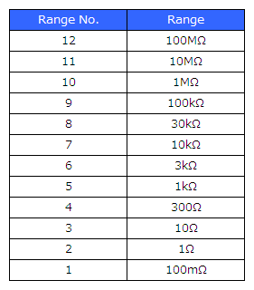
:CORRection:LOAD:DCResistance:CONDition 5,6,OFF,CC,5.23E-03 Range: 6 (3 kΩ range) |
Query |
:CORRection:LOAD:DCResistance:CONDition? 5 |
|
Response |
:CORRECTION:LOAD:DCRESISTANCE:CONDITION 6,OFF,CC,5.23E-03
(when HEADER ON) Range: 6 (3 kΩ range) |
|
Note |
If this command is executed and the setting last time was not the DC setting, the parameter to use for the reference value is changed to Rdc, and the reference value is cleared.
|
Syntax |
Command |
:CORRection:LOAD:DCResistance:REFerence <Compensation No.>,<Reference value> |
Query |
:CORRection:LOAD:DCResistance:REFerence? <Compensation No.> |
|
Response |
<Reference value> |
|
Parameter |
<Compensation No.> = 1/ 2/ 3/ 4/ 5 |
|
Explanation |
Command |
Sets the reference value to use for load compensation for when DC resistance measurement. This command is only valid when in LCR mode. |
Query |
Returns the reference value to use for load compensation for when DC resistance measurement. |
|
Example |
Command |
:CORRection:LOAD:DCResistance:REFerence 1,20 |
Query |
:CORRection:LOAD:DCResistance:REFerence? 1 |
|
Response |
:CORRECTION:LOAD:DCRESISTANCE:REFERENCE 20.00000E+00
(when HEADER ON) |
|
Note |
An execution error occurs in the following cases.
|
Syntax |
Command |
|
Query |
:CORRection:LOAD:DATA? <Compensation No.> |
|
Response |
<Compensation coefficient 1>, <Compensation coefficient 2> |
|
Parameter |
<Compensation No.> = 1/ 2/ 3/ 4/ 5 |
|
Explanation |
Command |
|
Query |
Returns the compensation coefficient acquired by executing load compensation. |
|
Example |
Command |
|
Query |
:CORRection:LOAD:DATA? 1 |
|
Response |
225.6614E-03, -61.187
|
|
Note |
If the compensation mode is DC, only <Compensation coefficient 1> is returned. |
Syntax |
Command |
|
Query |
:CORRection:LOAD:ERRor? |
|
Response |
<Result> |
|
Parameter |
<Result> = 0/ 1 (NR1) |
|
Explanation |
Command |
|
Query |
Returns the result of executing load compensation. 0: Load compensation ended normally. |
|
Example |
Command |
|
Query |
:CORRection:LOAD:ERRor? |
|
Response |
:CORRECTION:LOAD:ERROR 0
(when HEADER ON) |
|
Note |
|
Syntax |
Command |
:CORRection:LOAD:REFerence <Compensation No.>,<Mode No.>,<Reference value1>,<Reference value2> |
Query |
:CORRection:LOAD:REFerence? <Compensation No.> |
|
Response |
<Mode No.>,<Reference value1>,<Reference value2> |
|
Parameter |
<Compensation No.> = 1/ 2/ 3/ 4/ 5 |
|
Explanation |
Command |
Sets the parameter and reference values to use for the reference values for load compensation. |
Query |
Returns the parameter and reference values to use for the reference value for load compensation. |
|
Example |
Command |
:CORRection:LOAD:REFerence 1,2,10e-9,0.00014 |
Query |
:CORRection:LOAD:REFerence? 1 |
|
Response |
:CORRECTION:LOAD:REFERENCE 2,10.00000E-09,140.0000E-06
(when HEADER ON) |
|
Note |
An execution error occurs in the following cases.

|
Syntax |
Command |
:CORRection:LOAD:RESet <Compensation No.> |
Query |
|
|
Response |
|
|
Parameter |
<Compensation No.> = 1/ 2/ 3/ 4/ 5 |
|
Explanation |
Command |
Clears the load compensation conditions of the specified compensation number. |
Query |
|
|
Example |
Command |
:CORRection:LOAD:RESet 1 |
Query |
|
|
Response |
|
|
Note |
The load compensation conditions cannot be restored once they are cleared. |
Syntax |
Command |
:CORRection:LOAD:RETurn <OFF/ON> |
Query |
:CORRection:LOAD:RETurn? |
|
Response |
<OFF/ON> |
|
Parameter |
|
|
Explanation |
Command |
Sets the load compensation function. The compensation values are not acquired. OFF: Disables the load compensation function. |
Query |
Returns the setting of the load compensation function. |
|
Example |
Command |
:CORRection:LOAD:RETurn ON |
Query |
:CORRection:LOAD:RETurn? |
|
Response |
:CORRECTION:LOAD:RETURN ON
(when HEADER ON) |
|
Note |
|
Syntax |
Command |
:CORRection:CABLe <Cable length> |
Query |
:CORRection:CABLe? |
|
Response |
<Cable length> |
|
Parameter |
<Cable length> = 0/1 (NR1) |
|
Explanation |
Command |
Sets the cable length compensation function. |
Query |
Returns the setting of the cable length compensation function. 0: The cable length compensation function is set to 0 m. |
|
Example |
Command |
:CORRection:CABLe 1 |
Query |
:CORRection:CABLe? |
|
Response |
:CORRECTION:CABLE 1
(when HEADER ON) |
|
Note |
|
Syntax |
Command |
:CORRection:SCALe <OFF/ON> |
Query |
:CORRection:SCALe? |
|
Response |
<OFF/ON> |
|
Parameter |
|
|
Explanation |
Command |
Sets the scaling compensation function. |
Query |
Returns the setting of the scaling compensation function. |
|
Example |
Command |
:CORRection:SCALe ON |
Query |
:CORRection:SCALe? |
|
Response |
:CORRECTION:SCALE ON
(when HEADER ON) |
|
Note |
In analyzer mode, only scaling No. 1 and scaling No. 3 are enabled. |
Syntax |
Command |
:CORRection:SCALe:DATA <Scaling No.>,<Compensation value A>,<Compensation value B> |
Query |
:CORRection:SCALe:DATA? <Scaling No.> |
|
Response |
<Compensation value A>,<Compensation value B> |
|
Parameter |
<Scaling No.> = 1/ 2/ 3/ 4 |
|
Explanation |
Command |
Sets the values of the scaling compensation function. |
Query |
Returns the values of the scaling compensation function. |
|
Example |
Command |
:CORRection:SCALe:DATA 1,1.23,4.56 |
Query |
:CORRection:SCALe:DATA? 1 |
|
Response |
:CORRECTION:SCALE:DATA 1.23,4.560000E+00
(when HEADER ON) |
|
Note |
|
Syntax |
Command |
:DCBias <ON/OFF> |
Query |
:DCBias? |
|
Response |
<ON/OFF> |
|
Parameter |
|
|
Explanation |
Command |
Sets the DC bias function. |
Query |
Returns the setting of the DC bias function. |
|
Example |
Command |
:DCBias ON |
Query |
:DCBias? |
|
Response |
:DCBIAS ON
(when HEADER ON) |
|
Note |
|
Syntax |
Command |
:DCBias:LEVel <DC bias level> |
Query |
:DCBias:LEVel? |
|
Response |
<DC bias level> |
|
Parameter |
<DC bias level> = 0.00 to 2.50 V (NR2) |
|
Explanation |
Command |
Sets the DC bias level. |
Query |
Returns the DC bias level. |
|
Example |
Command |
:DCBias:LEVel 1.50 |
Query |
:DCBias:LEVel? |
|
Response |
:DCBIAS:LEVEL 1.50
(when HEADER ON) |
|
Note |
|
Syntax |
Command |
:DCResistance:ADJust <ON/OFF> |
Query |
:DCResistance:ADJust? |
|
Response |
<ON/OFF> |
|
Parameter |
|
|
Explanation |
Command |
Sets the DC offset for when DC resistance measurement. |
Query |
Returns the setting of the DC offset for when DC resistance measurement. |
|
Example |
Command |
:DCResistance:ADJust ON |
Query |
:DCResistance:ADJust? |
|
Response |
:DCRESISTANCE:ADJUST ON
(when HEADER ON) |
|
Note |
|
Syntax |
Command |
:DCResistance:ADJust:DEMand |
Query |
|
|
Response |
|
|
Parameter |
|
|
Explanation |
Command |
Acquires the DC offset value for when DC resistance measurement. |
Query |
|
|
Example |
Command |
:DCResistance:ADJust:DEMand |
Query |
|
|
Response |
|
|
Note |
|
Syntax |
Command |
:DCResistance:AVERaging <OFF/ number of averaging times> |
Query |
:DCResistance:AVERaging? |
|
Response |
<OFF/ number of averaging times> |
|
Parameter |
<number of averaging times> = 1 to 256 (NR1) |
|
Explanation |
Command |
Sets the number of averaging times for when DC resistance measurement. OFF: Disables the averaging function. |
Query |
Returns the number of averaging times for when DC resistance measurement. |
|
Example |
Command |
:DCResistance:AVERaging 32 |
Query |
:DCResistance:AVERaging? |
|
Response |
:DCRESISTANCE:AVERAGING 32
(when HEADER ON) |
|
Note |
Setting the number of averaging times to 1 automatically sets the averaging function to OFF. |
Syntax |
Command |
:DCResistance:DELay <Delay time> |
Query |
:DCResistance:DELay? |
|
Response |
<Delay time> |
|
Parameter |
<Delay time> = 0.0003 to 9.9999 (NR2) |
|
Explanation |
Command |
Sets the delay time for when switching between AC measurement and DC measurement. |
Query |
Returns the delay time for when switching between AC measurement and DC measurement. |
|
Example |
Command |
:DCResistance:DELay 0.05 |
Query |
:DCResistance:DELay? |
|
Response |
:DCRESISTANCE:DELAY 0.0500
(when HEADER ON) |
|
Note |
|
Syntax |
Command |
:DCResistance:LEVel <V/CV/CC> |
Query |
:DCResistance:LEVel? |
|
Response |
<V/CV/CC> |
|
Parameter |
|
|
Explanation |
Command |
Sets the measurement signal type for when DC resistance measurement to any one of opencircuit voltage, constant voltage, and constant current. V: Sets open-circuit voltage. |
Query |
Returns the measurement signal type for when DC resistance measurement. |
|
Example |
Command |
:DCResistance:LEVel V |
Query |
:DCResistance:LEVel? |
|
Response |
:DCRESISTANCE:LEVEL V
(when HEADER ON) |
|
Note |
|
Syntax |
Command |
:DCResistance:LEVel:CCURRent <Constant current level> |
Query |
:DCResistance:LEVel:CCURRent? |
|
Response |
<Constant current level> |
|
Parameter |
<Constant current level> = The settable range varies depending on the conditions. (NR3) |
|
Explanation |
Command |
Sets the constant current level for when DC resistance measurement. |
Query |
Returns the setting of the constant current level for when DC resistance measurement. |
|
Example |
Command |
:DCResistance:LEVel:CCURRent 10E-3 |
Query |
:DCResistance:LEVel:CCURRent? |
|
Response |
:DCRESISTANCE:LEVEL:CCURRENT 10.00E-03
(when HEADER ON) |
|
Note |
|
Syntax |
Command |
:DCResistance:LEVel:CVOLTage <Constant voltage level> |
Query |
:DCResistance:LEVel:CVOLTage? |
|
Response |
<Constant voltage level> |
|
Parameter |
<Constant voltage level> = The settable range varies depending on the conditions. (NR3) |
|
Explanation |
Command |
Sets the constant voltage level for when DC resistance measurement. |
Query |
Returns the setting of the constant voltage level for when DC resistance measurement. |
|
Example |
Command |
:DCResistance:LEVel:CVOLTage 1.000 |
Query |
:DCResistance:LEVel:CVOLTage? |
|
Response |
:DCRESISTANCE:LEVEL:CVOLTAGE 1.000
(when HEADER ON) |
|
Note |
|
Syntax |
Command |
:DCResistance:LEVel:VOLTage <Open-circuit voltage level> |
Query |
:DCResistance:LEVel:VOLTage? |
|
Response |
<Open-circuit voltage level> |
|
Parameter |
<Open-circuit voltage level> = The settable range varies depending on the conditions. (NR3) |
|
Explanation |
Command |
Sets the open-circuit voltage level for when DC resistance measurement. |
Query |
Returns the setting of the open-circuit voltage level for when DC resistance measurement. |
|
Example |
Command |
:DCResistance:LEVel:VOLTage 1.000 |
Query |
:DCResistance:LEVel:VOLTage? |
|
Response |
:DCRESISTANCE:LEVEL:VOLTAGE 1.000
(when HEADER ON) |
|
Note |
|
Syntax |
Command |
:DCResistance:LIMiter <ON/OFF> |
Query |
:DCResistance:LIMiter? |
|
Response |
<ON/OFF> |
|
Parameter |
|
|
Explanation |
Command |
Sets the limit function for when DC resistance measurement. |
Query |
Returns the setting of the limit function for when DC resistance measurement. |
|
Example |
Command |
:DCResistance:LIMiter ON |
Query |
:DCResistance:LIMiter? |
|
Response |
:DCRESISTANCE:LIMITER ON
(when HEADER ON) |
|
Note |
|
Syntax |
Command |
:DCResistance:LIMiter:CURRent <Current limit value> |
Query |
:DCResistance:LIMiter:CURRent? |
|
Response |
<Current limit value> |
|
Parameter |
<Current limit value> = 0.01 m to 100.00 mA (NR3) |
|
Explanation |
Command |
Sets the current limit value for when DC resistance measurement. |
Query |
Returns the current limit value for when DC resistance measurement. |
|
Example |
Command |
:DCResistance:LIMiter:CURRent 50.00E-03 |
Query |
:DCResistance:LIMiter:CURRent? |
|
Response |
:DCRESISTANCE:LIMITER:CURRENT 50.00E-03
(when HEADER ON) |
|
Note |
|
Syntax |
Command |
:DCResistance:LIMiter:VOLTage <Voltage limit value> |
Query |
:DCResistance:LIMiter:VOLTage? |
|
Response |
<Voltage limit value> |
|
Parameter |
<Voltage limit value> = 0.10 to 2.50 V (NR3) |
|
Explanation |
Command |
Sets the voltage limit value for when DC resistance measurement. |
Query |
Returns the voltage limit value for when DC resistance measurement. |
|
Example |
Command |
:DCResistance:LIMiter:VOLTage 2.5 |
Query |
:DCResistance:LIMiter:VOLTage? |
|
Response |
:DCRESISTANCE:LIMITER:VOLTAGE 2.500
(when HEADER ON) |
|
Note |
|
Syntax |
Command |
:DCResistance:RANGe <Range No.> |
Query |
:DCResistance:RANGe? |
|
Response |
<Range No.> |
|
Parameter |
<Measurement range No.> = 1 to 12 (NR1) |
|
Explanation |
Command |
Sets the measurement range for when DC resistance measurement. |
Query |
Returns the measurement range for when DC resistance measurement. |
|
Example |
Command |
:DCResistance:RANGe 4 |
Query |
:DCResistance:RANGe? |
|
Response |
:DCRESISTANCE:RANGE 4
(when HEADER ON) |
|
Note |
|
Syntax |
Command |
:DCResistance:RANGe:AUTO <ON/OFF> |
Query |
:DCResistance:RANGe:AUTO? |
|
Response |
<ON/OFF> |
|
Parameter |
|
|
Explanation |
Command |
Sets the measurement range for when DC resistance measurement to be changed automatically. ON: The range is changed automatically by the auto ranging function. |
Query |
Returns the automatic setting of the measurement range for when DC resistance measurement. |
|
Example |
Command |
:DCResistance:RANGe:AUTO ON |
Query |
:DCResistance:RANGe:AUTO? |
|
Response |
:DCRESISTANCE:RANGE:AUTO ON
(when HEADER ON) |
|
Note |
|
Syntax |
Command |
:DCResistance:RANGe:LOWZ <ON/OFF> |
Query |
:DCResistance:RANGe:LOWZ? |
|
Response |
<ON/OFF> |
|
Parameter |
|
|
Explanation |
Command |
Sets low Z high accuracy mode for when DC resistance measurement. |
Query |
Returns the setting of low Z high accuracy mode for when DC resistance measurement. |
|
Example |
Command |
:DCResistance:RANGe:LOWZ ON |
Query |
:DCResistance:RANGe:LOWZ? |
|
Response |
:DCRESISTANCE:RANGE:LOWZ ON
(when HEADER ON) |
|
Note |
|
Syntax |
Command |
:DCResistance:SPEEd <FAST/MEDium/SLOW/SLOW2> |
Query |
:DCResistance:SPEEd? |
|
Response |
<FAST/MEDIUM/SLOW/SLOW2> |
|
Parameter |
|
|
Explanation |
Command |
Sets the measurement speed for when DC resistance measurement. |
Query |
Returns the setting of the measurement speed for when DC resistance measurement. |
|
Example |
Command |
:DCResistance:SPEEd MEDium |
Query |
:DCResistance:SPEEd? |
|
Response |
:DCRESISTANCE:SPEED MEDIUM
(when HEADER ON) |
|
Note |
|
Syntax |
Command |
:DISPlay <ON/OFF> |
Query |
:DISPlay? |
|
Response |
<ON/OFF> |
|
Parameter |
|
|
Explanation |
Command |
Sets LCD display. ON: Sets the LCD to always on. |
Query |
Returns the setting of LCD display. |
|
Example |
Command |
:DISPlay OFF |
Query |
:DISPlay? |
|
Response |
:DISPLAY OFF
(when HEADER ON) |
|
Note |
|
Syntax |
Command |
:ESE0 <Mask value> |
Query |
:ESE0? |
|
Response |
<Mask value> |
|
Parameter |
<Mask value> = 0 to 255 (NR1) |
|
Explanation |
Command |
Sets the mask pattern of ESER0. |
Query |
Returns the mask pattern of ESER0. |
|
Example |
Command |
:ESE0 20 |
Query |
:ESE0? |
|
Response |
:ESE0 20
(when HEADER ON) |
|
Note |
For details on each of the bits, refer to "About Event Registers". |
Syntax |
Command |
:ESE1 <Mask value> |
Query |
:ESE1? |
|
Response |
<Mask value> |
|
Parameter |
<Mask value> = 0 to 255 (NR1) |
|
Explanation |
Command |
Sets the mask pattern of ESER1. |
Query |
Returns the mask pattern of ESER1. |
|
Example |
Command |
:ESE1 64 |
Query |
:ESE1? |
|
Response |
:ESE1 64
(when HEADER ON) |
|
Note |
This register's bits are reset after 1 measurement completes. |
Syntax |
Command |
:ESE2 <Mask value> |
Query |
:ESE2? |
|
Response |
<Mask value> |
|
Parameter |
<Mask value> = 0 to 255 (NR1) |
|
Explanation |
Command |
Sets the mask pattern of ESER2. |
Query |
Returns the mask pattern of ESER2. |
|
Example |
Command |
:ESE2 1 |
Query |
:ESE2? |
|
Response |
:ESE2 1
(when HEADER ON) |
|
Note |
For details on each of the bits, refer to "About Event Registers". |
Syntax |
Command |
:ESE3 <Mask value> |
Query |
:ESE3? |
|
Response |
<Mask value> |
|
Parameter |
<Mask value> = 0 to 255 (NR1) |
|
Explanation |
Command |
Sets the mask pattern of ESER3. |
Query |
Returns the mask pattern of ESER3. |
|
Example |
Command |
:ESE3 3 |
Query |
:ESE3? |
|
Response |
:ESE3 3
(when HEADER ON) |
|
Note |
For details on each of the bits, refer to "About Event Registers". |
Syntax |
Command |
|
Query |
:ESR0? |
|
Response |
<Register value> |
|
Parameter |
<Register value> = 0 to 255 (NR1) |
|
Explanation |
Command |
|
Query |
Returns the register value of event status register 0 (ESR0), and clears the register. |
|
Example |
Command |
|
Query |
:ESR0? |
|
Response |
4
|
|
Note |
This register's bits are reset after 1 measurement completes. |
Syntax |
Command |
|
Query |
:ESR1? |
|
Response |
<Register value> |
|
Parameter |
<Register value> = 0 to 255 (NR1) |
|
Explanation |
Command |
|
Query |
Returns the register value of event status register 1 (ESR1), and clears the register. |
|
Example |
Command |
|
Query |
:ESR1? |
|
Response |
82
|
|
Note |
When comparator measurement is performed in LCR mode, the bits are set after one measurement finishes. |
Syntax |
Command |
|
Query |
:ESR2? |
|
Response |
<Register value> |
|
Parameter |
<Register value> = 0 to 255 (NR1) |
|
Explanation |
Command |
|
Query |
Returns the register value of event status register 2 (ESR2), and clears the register. |
|
Example |
Command |
|
Query |
:ESR2? |
|
Response |
1
|
|
Note |
When BIN measurement is performed in LCR mode, the bits are set after one measurement finishes. |
Syntax |
Command |
|
Query |
:ESR3? |
|
Response |
<Register value> |
|
Parameter |
<Register value> = 0 to 255 (NR1) |
|
Explanation |
Command |
|
Query |
Returns the register value of event status register 3 (ESR3), and clears the register. |
|
Example |
Command |
|
Query |
:ESR3? |
|
Response |
64
|
|
Note |
When BIN measurement is performed in LCR mode, the bits are set after one measurement finishes. |
Syntax |
Command |
:FILE:DATE <ON/OFF> |
Query |
:FILE:DATE? |
|
Response |
<ON/OFF> |
|
Parameter |
|
|
Explanation |
Command |
Sets whether to save the date and time when saving text. |
Query |
Returns the date and time setting for when saving text. |
|
Example |
Command |
:FILE:DATE ON |
Query |
:FILE:DATE? |
|
Response |
:FILE:DATE ON
(when HEADER ON) |
|
Note |
|
Syntax |
Command |
:FILE:DELIMiter <COMma/TAB/SEMIcolon/SPACE> |
Query |
:FILE:DELIMiter? |
|
Response |
<COMMA/TAB/SEMICOLON/SPACE> |
|
Parameter |
|
|
Explanation |
Command |
Sets the delimiter for when saving text. TAB: Tab |
Query |
Returns the delimiter for when saving text. |
|
Example |
Command |
:FILE:DELIMiter SEMIcolon |
Query |
:FILE:DELIMiter? |
|
Response |
:FILE:DELIMITER SEMICOLON
(when HEADER ON) |
|
Note |
|
Syntax |
Command |
:FILE:FOLDer <Folder name> |
Query |
:FILE:FOLDer? |
|
Response |
<Folder name> |
|
Parameter |
<Folder name> = 0 to 9, A to Z, + ,-, _ (Up to 12 characters) |
|
Explanation |
Command |
Sets the folder name of the save folder. |
Query |
Returns the folder name of the save folder. |
|
Example |
Command |
:FILE:FOLDer SaveData0523 |
Query |
:FILE:FOLDer? |
|
Response |
:FILE:FOLDER SAVEDATA0523
(when HEADER ON) |
|
Note |
Executing this command automatically sets the mode of the save folder to "MANUAL". |
Syntax |
Command |
|
Query |
:FILE:INFOrmation? |
|
Response |
<Format type>,<Total size>,<Space used>,<Space free>,<Usage rate> |
|
Parameter |
<Format type> = FAT12/ FAT16/ FAT32 |
|
Explanation |
Command |
|
Query |
Returns the information of the USB flash drive. |
|
Example |
Command |
|
Query |
:FILE:INFOrmation? |
|
Response |
:FILE:INFORMATION FAT32,1.9GB,960MB,949MB,50.3%
(when HEADER ON) |
|
Note |
|
Syntax |
Command |
:FILE:MODE <AUTO/MANUAL> |
Query |
:FILE:MODE? |
|
Response |
<AUTO/MANUAL> |
|
Parameter |
|
|
Explanation |
Command |
Sets the mode of the save folder. AUTO: The save folder is set automatically from the date and time. |
Query |
Returns the mode of the save folder. |
|
Example |
Command |
:FILE:MODE MANUAL |
Query |
:FILE:MODE? |
|
Response |
:FILE:MODE MANUAL
(when HEADER ON) |
|
Note |
|
Syntax |
Command |
:FILE:PANel:SAVE <Panel name> |
Query |
|
|
Response |
|
|
Parameter |
<Panel name> = +, -, _, 0 to 9, A to Z (12 characters or less) |
|
Explanation |
Command |
Specifies a panel name and saves the panel to USB memory. |
Query |
|
|
Example |
Command |
:FILE:PANel:SAVE TEST1 |
Query |
|
|
Response |
|
|
Note |
Before executing this command, check whether the USB memory has been properly recognized. |
Syntax |
Command |
:FILE:PANel:LOAD <Panel name> |
Query |
|
|
Response |
|
|
Parameter |
<Panel name> = +, -, _, 0 to 9, A to Z (12 characters or less) |
|
Explanation |
Command |
Specifies a panel name and executes a panel load from USB memory. |
Query |
|
|
Example |
Command |
:FILE:PANel:LOAD TEST1 |
Query |
|
|
Response |
|
|
Note |
An execution error will result if a panel with the specified name does not exist. |
Syntax |
Command |
:FILE:PANel:ALLSave <Specified save folder name> |
Query |
|
|
Response |
|
|
Parameter |
<Panel name> = +, -, _, 0 to 9, A to Z (12 characters or less) |
|
Explanation |
Command |
Specifies a panel name and saves the current panel and all the panels saved in the instrument to USB memory. |
Query |
|
|
Example |
Command |
:FILE:PANel:ALLSave TEST2 |
Query |
|
|
Response |
|
|
Note |
Before executing this command, check whether the USB memory has been properly recognized. |
Syntax |
Command |
:FILE:PANel:ALLLoad <Specified save folder name> |
Query |
|
|
Response |
|
|
Parameter |
<Panel name> = +, -, _, 0 to 9, A to Z (12 characters or less) |
|
Explanation |
Command |
Specifies a panel name and executes all load from the USB memory. |
Query |
|
|
Example |
Command |
:FILE:PANel:ALLLoad TEST2 |
Query |
|
|
Response |
|
|
Note |
An execution error will result if a folder with the specified name does not exist. |
Syntax |
Command |
:FILE:PARAmeter <ON/OFF> |
Query |
:FILE:PARAmeter? |
|
Response |
<ON/OFF> |
|
Parameter |
|
|
Explanation |
Command |
Sets whether to save the measurement parameters when saving text. |
Query |
Returns the setting of the measurement parameters for when saving text. |
|
Example |
Command |
:FILE:PARAmeter ON |
Query |
:FILE:PARAmeter? |
|
Response |
:FILE:PARAMETER ON
(when HEADER ON) |
|
Note |
|
Syntax |
Command |
:FILE:QUOTe <OFF/DOUBle/SINGle> |
Query |
:FILE:QUOTe? |
|
Response |
<OFF/DOUBLE/SINGLE> |
|
Parameter |
|
|
Explanation |
Command |
Sets the quotation mark for when saving text. OFF: Quotation marks are not added. |
Query |
Returns the quotation mark for when saving text. |
|
Example |
Command |
:FILE:QUOTe DOUBle |
Query |
:FILE:QUOTe? |
|
Response |
:FILE:QUOTE DOUBLE
(when HEADER ON) |
|
Note |
|
Syntax |
Command |
:FILE:SAVE |
Query |
|
|
Response |
|
|
Parameter |
|
|
Explanation |
Command |
Executes file saving. |
Query |
|
|
Example |
Command |
:FILE:SAVE |
Query |
|
|
Response |
|
|
Note |
|
Syntax |
Command |
:FILE:SET <ON/OFF> |
Query |
:FILE:SET? |
|
Response |
<ON/OFF> |
|
Parameter |
|
|
Explanation |
Command |
Sets whether to save the measurement conditions when saving text. |
Query |
Returns the measurement condition setting for when saving text. |
|
Example |
Command |
:FILE:SET ON |
Query |
:FILE:SET? |
|
Response |
:FILE:SET ON
(when HEADER ON) |
|
Note |
|
Syntax |
Command |
:FILE:TYPE:TEXT <OFF/ON> |
Query |
:FILE:TYPE:TEXT? |
|
Response |
<OFF/ON> |
|
Parameter |
|
|
Explanation |
Command |
Configures the text save setting. OFF: Text data is not saved. |
Query |
Returns the text save setting. |
|
Example |
Command |
:FILE:TYPE:TEXT ON |
Query |
:FILE:TYPE:TEXT? |
|
Response |
:FILE:TYPE:TEXT ON
(when HEADER ON) |
|
Note |
This command configures save settings but does not actually save data. |
Syntax |
Command |
:FILE:TYPE:BMP <OFF/COLor/MONochrome> |
Query |
:FILE:TYPE:BMP? |
|
Response |
<OFF/COLOR/MONOCHROME> |
|
Parameter |
|
|
Explanation |
Command |
Configures the BMP save setting. OFF: BMP data is not saved. |
Query |
Returns the BMP save setting. |
|
Example |
Command |
:FILE:TYPE:BMP COLOR |
Query |
:FILE:TYPE:BMP? |
|
Response |
:FILE:TYPE:BMP COLOR
(when HEADER ON) |
|
Note |
This command configures save settings but does not actually save data. |
Syntax |
Command |
:FORMat:DATA <ASCii/REAL> |
Query |
:FORMat:DATA? |
|
Response |
<ASCII/REAL> |
|
Parameter |
|
|
Explanation |
Command |
Sets the data transfer format. ASCii: Transfers data in ASCII format. |
Query |
Returns the data transfer format. |
|
Example |
Command |
:FORMat:DATA REAL |
Query |
:FORMat:DATA? |
|
Response |
:FORMAT:DATA REAL
(when HEADER ON) |
|
Note |
|
Syntax |
Command |
:FORMat:LONG <ON/OFF> |
Query |
:FORMat:LONG? |
|
Response |
<ON/OFF> |
|
Parameter |
|
|
Explanation |
Command |
Sets long format for when data transfer. |
Query |
Returns ON or OFF for the setting of long format for when data transfer. |
|
Example |
Command |
:FORMat:LONG ON |
Query |
:FORMat:LONG? |
|
Response |
:FORMAT:LONG ON
(when HEADER ON) |
|
Note |
|
Syntax |
Command |
:FREQuency <Frequency> |
Query |
:FREQuency? |
|
Response |
<Frequency> |
|
Parameter |
<Frequency> = 4.00 to 5.0000 MHz (NR3) |
|
Explanation |
Command |
Sets the measurement frequency. |
Query |
Returns the setting of the measurement frequency. |
|
Example |
Command |
:FREQuency 1000 |
Query |
:FREQuency? |
|
Response |
:FREQUENCY 1.0000E+03
(when HEADER ON) |
|
Note |
|
Syntax |
Command |
:HANDshake <OFF/HARDware/X/BOTH> |
Query |
:HANDshake? |
|
Response |
<OFF/HARDware/X/BOTH> |
|
Parameter |
|
|
Explanation |
Command |
Sets the RS-232C communication handshake. OFF: No handshake |
Query |
Returns the RS-232C communication handshake. |
|
Example |
Command |
:HANDshake X |
Query |
:HANDshake? |
|
Response |
:HANDSHAKE X
(when HEADER ON) |
|
Note |
An execution error occurs if the interface is set to other than RS-232C. |
Syntax |
Command |
|
Query |
:HCOPy:DATA? <COLor/MONochrome> |
|
Response |
<BMP data> |
|
Parameter |
|
|
Explanation |
Command |
|
Query |
Returns the BMP data of the measurement screen in binary format. COLor: Color BMP data |
|
Example |
Command |
|
Query |
:HCOPy:DATA? COLor |
|
Response |
Acquires the color measurement screens. |
|
Note |
For the procedure to convert the binary data obtained by this query to the BMP, refer to the sample program. |
Syntax |
Command |
:HEADer <ON/OFF> |
Query |
:HEADer? |
|
Response |
|
|
Parameter |
|
|
Explanation |
Command |
Sets whether or not there is a header in the response message. |
Query |
Returns the header setting of the response message. |
|
Example |
Command |
:HEADer ON |
Query |
:HEADer? |
|
Response |
:HEADER ON
(when HEADER ON) |
|
Note |
|
Syntax |
Command |
:HIZ <ON/OFF> |
Query |
:HIZ? |
|
Response |
<ON/OFF> |
|
Parameter |
|
|
Explanation |
Command |
Enables or disables the Hi Z reject function. OFF: Does not detect abnormal measurement values. |
Query |
Returns whether the Hi Z reject function is enabled or disabled. |
|
Example |
Command |
:HIZ ON |
Query |
:HIZ? |
|
Response |
:HIZ ON
(when HEADER ON) |
|
Note |
|
Syntax |
Command |
:HIZ:LIMit <Limit value> |
Query |
:HIZ:LIMit? |
|
Response |
<Limit value> |
|
Parameter |
<Limit value> = 0 to 30000% (NR1) |
|
Explanation |
Command |
Sets the limit value of the Hi Z reject function. |
Query |
Returns the limit value of the Hi Z reject function. |
|
Example |
Command |
:HIZ:LIMit 500 |
Query |
:HIZ:LIMit? |
|
Response |
:HIZ:LIMIT 500
(when HEADER ON) |
|
Note |
|
Syntax |
Command |
:IO:EOM:MODE <HOLD/PULSe> |
Query |
:IO:EOM:MODE? |
|
Response |
|
|
Parameter |
|
|
Explanation |
Command |
Sets the INDEX and EOM output method. |
Query |
Returns the INDEX and EOM output method. |
|
Example |
Command |
:IO:EOM:MODE PULSE |
Query |
:IO:EOM:MODE? |
|
Response |
:IO:EOM:MODE PULSE
(when HEADER ON) |
|
Note |
For a timing chart describing the setting made with this command, see the "External Control" chapter in the instrument's user manual. |
Syntax |
Command |
:IO:EOM:PULSe <Pulse width> |
Query |
:IO:EOM:PULSe? |
|
Response |
|
|
Parameter |
<Pulse width> = 0.0001 to 0.9999s (NR2) |
|
Explanation |
Command |
Sets the pulse width for which to keep EOM low (on). |
Query |
Returns the pulse width for which to keep EOM low (on). |
|
Example |
Command |
:IO:EOM:PULSe 0.002 |
Query |
:IO:EOM:PULSe? |
|
Response |
:IO:EOM:PULSE 0.0020
(when HEADER ON) |
|
Note |
For a timing chart describing the setting made with this command, see the "External Control" chapter in the instrument's user manual. |
Syntax |
Command |
:IO:OUTPut:DELay <I/O delay time> |
Query |
:IO:OUTPut:DELay? |
|
Response |
<I/O delay time> |
|
Parameter |
<I/O delay time> = 0 to 0.9999 s (NR2) |
|
Explanation |
Command |
Sets the delay time for the period between the output of comparator and BIN judgment results and the output of the EOM from the EXT I/O. |
Query |
Returns the delay time for the period between the output of comparator and BIN judgment results and the output of the EOM from the EXT I/O. |
|
Example |
Command |
:IO:OUTPUT:DELAY 0.1234 |
Query |
:IO:OUTPUT:DELAY? |
|
Response |
:IO:OUTPUT:DELAY 0.1234
(when HEADER ON) |
|
Note |
The delay time for the period between the comparator and BIN judgment results and the EOM has an error of approximately 160 ms with regards to the setting value. |
Syntax |
Command |
:IO:RESult:RESet <ON/OFF> |
Query |
:IO:RESult:RESet? |
|
Response |
<ON/OFF> |
|
Parameter |
|
|
Explanation |
Command |
Sets whether the judgment result signal line of the EXT I/O is reset. ON: Resets the judgment results simultaneously with the input of a measurement start signal (trigger signal). |
Query |
Returns whether the judgment result signal line of the EXT I/O is reset. |
|
Example |
Command |
:IO:RESult:RESet ON |
Query |
:IO:RESult:RESet? |
|
Response |
:IO:RESULT:RESET ON
(when HEADER ON) |
|
Note |
For details on the judgment result signal line, refer to "External Control" in the instruction manual. |
Syntax |
Command |
:IO:TRIGger:EDGe <DOWN/UP> |
Query |
:IO:TRIGger:EDGe? |
|
Response |
<DOWN/UP> |
|
Parameter |
|
|
Explanation |
Command |
Sets the trigger edge of the EXT I/O. DOWN: Applies a trigger to the rising edge. |
Query |
Returns the setting of the trigger edge of the EXT I/O. |
|
Example |
Command |
:IO:TRIGger:EDGe UP |
Query |
:IO:TRIGger:EDGe? |
|
Response |
:IO:TRIGGER:EDGE UP
(when HEADER ON) |
|
Note |
|
Syntax |
Command |
:IO:TRIGger:ENABle <ON/OFF> |
Query |
:IO:TRIGger:ENABle? |
|
Response |
<ON/OFF> |
|
Parameter |
|
|
Explanation |
Command |
Enables or disables trigger input from the EXT I/O during measurement. ON: Accepts trigger input from the EXT I/O during measurement. |
Query |
Returns whether trigger input from the EXT I/O during measurement is enabled or disabled. |
|
Example |
Command |
:IO:TRIGger:ENABle ON |
Query |
:IO:TRIGger:ENABle? |
|
Response |
:IO:TRIGGER:ENABLE ON
(when HEADER ON) |
|
Note |
|
Syntax |
Command |
:KEYLock |
Query |
:KEYLock? |
|
Response |
<ON/OFF> |
|
Parameter |
|
|
Explanation |
Command |
Enables the key lock. |
Query |
Returns the state of the key lock. OFF: The key lock is not enabled. |
|
Example |
Command |
:KEYLock |
Query |
:KEYLock? |
|
Response |
:KEYLOCK ON
(when HEADER ON) |
|
Note |
An execution error occurs if this command is sent while the key lock is enabled. |
Syntax |
Command |
:KEYLock:PASScode <Passcode/ none> |
Query |
|
|
Response |
|
|
Parameter |
<Passcode> = 0 to 9 (up to 4 digits) |
|
Explanation |
Command |
Sets the passcode of the key lock. |
Query |
|
|
Example |
Command |
:KEYLock:PASScode 0523 |
Query |
|
|
Response |
|
|
Note |
An execution error occurs in the following cases.
|
Syntax |
Command |
:KEYLock:UNLock <Passcode/ none> |
Query |
|
|
Response |
|
|
Parameter |
<Passcode> = 0 to 9 (up to 4 digits) |
|
Explanation |
Command |
Disables the key lock. |
Query |
|
|
Example |
Command |
:KEYLock:UNLock 0523 |
Query |
|
|
Response |
|
|
Note |
An execution error occurs in the following cases.
|
Syntax |
Command |
:LEVel <V/CV/CC> |
Query |
:LEVel? |
|
Response |
<V/CV/CC> |
|
Parameter |
|
|
Explanation |
Command |
Sets the measurement signal type to any one of open-circuit voltage, constant voltage, and constant current. V: Sets open-circuit voltage. |
Query |
Returns the measurement signal type. |
|
Example |
Command |
:LEVel V |
Query |
:LEVel? |
|
Response |
:LEVEL V
(when HEADER ON) |
|
Note |
|
Syntax |
Command |
:LEVel:CCURRent <Constant current level> |
Query |
:LEVel:CCURRent? |
|
Response |
<Constant current level> |
|
Parameter |
<Constant current level> = The settable range varies depending on the conditions. (NR3) |
|
Explanation |
Command |
Sets the constant current level. |
Query |
Returns the currently set constant current level. |
|
Example |
Command |
:LEVel:CCURRent 10E-3 |
Query |
:LEVel:CCURRent? |
|
Response |
:LEVEL:CCURRENT 10.00E-03
(when HEADER ON) |
|
Note |
|
Syntax |
Command |
:LEVel:CHECk <ON/OFF> |
Query |
:LEVel:CHECk? |
|
Response |
<ON/OFF> |
|
Parameter |
|
|
Explanation |
Command |
Sets the detection level monitoring function. |
Query |
Returns the setting of the detection level monitoring function. |
|
Example |
Command |
:LEVel:CHECk ON |
Query |
:LEVel:CHECk? |
|
Response |
:LEVEL:CHECK ON
(when HEADER ON) |
|
Note |
|
Syntax |
Command |
:LEVel:CHECk:LIMit <Threshold value> |
Query |
:LEVel:CHECk:LIMit? |
|
Response |
<Threshold value> |
|
Parameter |
<Threshold value> = 0.01% to 100.00% (NR2) |
|
Explanation |
Command |
Sets the threshold value for judging a detection level error. |
Query |
Returns the threshold value for judging a detection level error. |
|
Example |
Command |
:LEVel:CHECk:LIMit 5.23 |
Query |
:LEVel:CHECk:LIMit? |
|
Response |
:LEVEL:CHECK:LIMIT 5.23
(when HEADER ON) |
|
Note |
|
Syntax |
Command |
:LEVel:CVOLTage <Constant voltage level> |
Query |
:LEVel:CVOLTage? |
|
Response |
<Constant voltage level> |
|
Parameter |
<Constant voltage level> = The settable range varies depending on the conditions. (NR3) |
|
Explanation |
Command |
Sets the constant voltage level. |
Query |
Returns the currently set constant voltage level. |
|
Example |
Command |
:LEVel:CVOLTage 1.000 |
Query |
:LEVel:CVOLTage? |
|
Response |
:LEVEL:CVOLTAGE 1.000
(when HEADER ON) |
|
Note |
|
Syntax |
Command |
:LEVel:VOLTage <Open-circuit voltage level> |
Query |
:LEVel:VOLTage? |
|
Response |
<Open-circuit voltage level> |
|
Parameter |
<Open-circuit voltage level> = The settable range varies depending on the conditions. (NR3) |
|
Explanation |
Command |
Sets the open-circuit voltage level. |
Query |
Returns the currently set open-circuit voltage level. |
|
Example |
Command |
:LEVel:VOLTage 1.000 |
Query |
:LEVel:VOLTage? |
|
Response |
:LEVEL:VOLTAGE 1.000
(when HEADER ON) |
|
Note |
|
Syntax |
Command |
:LEVel:OVER <Setting value> |
Query |
:LEVel:OVER? |
|
Response |
<Setting value> |
|
Parameter |
<Setting value> = 1 to 32 (NR1) |
|
Explanation |
Command |
Sets the detection sensitivity for measurement errors. |
Query |
Returns the setting of the detection sensitivity for measurement errors. |
|
Example |
Command |
:LEVel:OVER 3 |
Query |
:LEVel:OVER? |
|
Response |
:LEVEL:OVER 3
(when HEADER ON) |
|
Note |
Increase the setting value which defines the error of the measurement signal to reduce the detection sensitivity for measurement errors so that you can reduce the frequency of measurement error occurrence. |
Syntax |
Command |
:LIMiter <ON/OFF> |
Query |
:LIMiter? |
|
Response |
<ON/OFF> |
|
Parameter |
|
|
Explanation |
Command |
Sets the limit function. |
Query |
Returns the setting of the limit function. |
|
Example |
Command |
:LIMiter ON |
Query |
:LIMiter? |
|
Response |
:LIMITER ON
(when HEADER ON) |
|
Note |
|
Syntax |
Command |
:LIMiter:CURRent <Current limit value> |
Query |
:LIMiter:CURRent? |
|
Response |
<Current limit value> |
|
Parameter |
<Current limit value> = 0.01 m to 100.00 mA (NR3) |
|
Explanation |
Command |
Sets the current limit value. |
Query |
Returns the current limit value. |
|
Example |
Command |
:LIMiter:CURRent 50.00E-03 |
Query |
:LIMiter:CURRent? |
|
Response |
:LIMITER:CURRENT 50.00E-03
(when HEADER ON) |
|
Note |
|
Syntax |
Command |
:LIMiter:VOLTage <Voltage limit value> |
Query |
:LIMiter:VOLTage? |
|
Response |
<Voltage limit value> |
|
Parameter |
<Voltage limit value> = 0.005 to 5.000 V (NR3) |
|
Explanation |
Command |
Sets the voltage limit value. |
Query |
Returns the voltage limit value. |
|
Example |
Command |
:LIMiter:VOLTage 5.000 |
Query |
:LIMiter:VOLTage? |
|
Response |
:LIMITER:VOLTAGE 5.000
(when HEADER ON) |
|
Note |
|
Syntax |
Command |
:LOAD <Panel No.> |
Query |
|
|
Response |
|
|
Parameter |
<Panel No.> = 1 to 128 |
|
Explanation |
Command |
Loads the specified panel number. |
Query |
|
|
Example |
Command |
:LOAD 2 |
Query |
|
|
Response |
|
|
Note |
|
Syntax |
Command |
|
Query |
:MEASure? |
|
Response |
<Measurement value> |
|
Parameter |
|
|
Explanation |
Command |
|
Query |
For more detail, refer to "Querying measurement data". |
|
Example |
Command |
|
Query |
|
|
Response |
|
|
Note |
|
Syntax |
Command |
:MEASure:ITEM <MR0>, <MR1> |
Query |
:MEASure:ITEM? |
|
Response |
<MR0>, <MR1> |
|
Parameter |
<MR0> = 0 to 255 (NR1) |
|
Explanation |
Command |
Specifies the measurement parameter for response of the :MEASure? query during normal measurement by the sum of bits. |
Query |
Returns the measurement parameters for the response of the :MEASure? query during normal measurement. |
|
Example |
Command |
:MEASure:ITEM 53,18 |
Query |
:MEASure:ITEM? |
|
Response |
:MEASURE:ITEM 53,18
(when HEADER ON) |
|
Note |
Specify the MR0 and MR1 values by the sum of bits. |
Syntax |
Command |
:MEASure:OUTPut:AUTO <ON/OFF> |
Query |
:MEASure:OUTPut:AUTO? |
|
Response |
<ON/OFF> |
|
Parameter |
|
|
Explanation |
Command |
Sets the measurement value automatic output function. ON: Outputs the measurement values automatically after measurement finishes. If this is set to ON, the measurement values are automatically output from the selected interface after measurement finishes. |
Query |
Returns the setting of the measurement value automatic output function. |
|
Example |
Command |
:MEASure:OUTPut:AUTO ON |
Query |
:MEASure:OUTPut:AUTO? |
|
Response |
:MEASURE:OUTPUT:AUTO ON
(when HEADER ON) |
|
Note |
|
Syntax |
Command |
:MEASure:VALid <Setting value> |
Query |
:MEASure:VALid? |
|
Response |
<Setting value> |
|
Parameter |
<Setting value> = 1 to 255 (NR1) |
|
Explanation |
Command |
Sets the content for the response of the :MEASure? query by the sum of bits. |
Query |
Returns the content for the response of the :MEASure? query. |
|
Example |
Command |
:MEASure:VALid 18 |
Query |
:MEASure:VALid? |
|
Response |
:MEASURE:VALID 18
(when HEADER ON) |
|
Note |
|
Syntax |
Command |
|
Query |
:MEMory? <No data/ ALL> |
|
Response |
Refer to the response format of the MEASure? command. |
|
Parameter |
|
|
Explanation |
Command |
|
Query |
In the case of :MEMory? ALLSlash (/)
|
|
Example |
Command |
|
Query |
:MEMory? |
|
Response |
Z 1.590062E+03,PHASE -89.992 |
|
Note |
An execution error occurs during continuous measurement. |
Syntax |
Command |
:MEMory:CLEar |
Query |
|
|
Response |
|
|
Parameter |
|
|
Explanation |
Command |
Clears all of the measurement values saved to internal memory with the measurement value memory function. |
Query |
|
|
Example |
Command |
:MEMory:CLEar |
Query |
|
|
Response |
|
|
Note |
|
Syntax |
Command |
:MEMory:CONTrol <ON/IN/OFF> |
Query |
:MEMory:CONTrol? |
|
Response |
<ON/IN/OFF> |
|
Parameter |
|
|
Explanation |
Command |
Sets the measurement value memory function. OFF: Measurement values are not saved to internal memory. |
Query |
Returns the setting of the measurement value memory function. |
|
Example |
Command |
:MEMory:CONTrol ON |
Query |
:MEMory:CONTrol? |
|
Response |
:MEMORY:CONTROL ON
(when HEADER ON) |
|
Note |
An execution error occurs during continuous measurement. |
Syntax |
Command |
|
Query |
:MEMory:COUNt? |
|
Response |
<Number of data items> |
|
Parameter |
<Number of data items> = 0 to 32000 (NR1) |
|
Explanation |
Command |
|
Query |
Returns the number of data items saved to memory with the measurement value memory function. |
|
Example |
Command |
|
Query |
:MEMory:COUNt? |
|
Response |
1000
|
|
Note |
|
Syntax |
Command |
:MEMory:POINts <Memory size> |
Query |
:MEMory:POINts? |
|
Response |
<Memory size> |
|
Parameter |
<Memory size> = 1 to 32000 (NR1) |
|
Explanation |
Command |
Sets the number of data items to save to internal memory. |
Query |
Returns the number of data items to save to internal memory. |
|
Example |
Command |
:MEMory:POINts 200 |
Query |
:MEMory:POINts? |
|
Response |
:MEMORY:POINTS 200
(when HEADER ON) |
|
Note |
An execution error occurs during continuous measurement. |
Syntax |
Command |
:MEMory:SAVE |
Query |
|
|
Response |
|
|
Parameter |
|
|
Explanation |
Command |
Copies data saved to internal memory with the measured value memory function to USB memory. |
Query |
|
|
Example |
Command |
:MEMory:SAVE |
Query |
|
|
Response |
|
|
Note |
If data has not been saved in internal memory, an execution error will result. |
Syntax |
Command |
:MODE <LCR/ANALyzer/CONTinuous> |
Query |
:MODE? |
|
Response |
<LCR/ANALYZER/CONTINUOUS> |
|
Parameter |
|
|
Explanation |
Command |
Sets measurement mode. LCR : Sets measurement mode to LCR mode. |
Query |
Returns the setting of measurement mode. |
|
Example |
Command |
:MODE ANALyzer |
Query |
:MODE? |
|
Response |
:MODE ANALYZER
(when HEADER ON) |
|
Note |
|
Syntax |
Command |
|
Query |
:MONItor? |
|
Response |
<AC voltage monitor value>,<AC current monitor value>,<DC voltage monitor value>,<DC current monitor value> |
|
Parameter |
|
|
Explanation |
Command |
|
Query |
Returns the voltage monitor value and current monitor value. |
|
Example |
Command |
|
Query |
:MONItor? |
|
Response |
:MONITOR 3.500061E-03,1.015322E-02,3.361863E-03,9.767721E-03
(when HEADER ON) |
|
Note |
When only DC measurement is performed, the AC voltage monitor value and AC current monitor value become 0.000000E+00. |
Syntax |
Command |
:PARameter# <Z/ Y/ PHASE(phase angle)/ CS/ CP/ D/ LS/ LP/Q/ RS/ G/ RP/ X/B/ RDC/ OFF> |
Query |
:PARameter#? |
|
Response |
<Z/ Y/ PHASE(phase angle)/ CS/ CP/ D/ LS/ LP/Q/ RS/ G/ RP/ X/ B/ RDC/ OFF> |
|
Parameter |
|
|
Explanation |
Command |
Sets the display parameters |
Query |
Returns the settings of the display parameters. |
|
Example |
Command |
:PARameter1 Z;:PARameter3 PHASe |
Query |
:PARameter3? |
|
Response |
:PARAMETER3 PHASE
(when HEADER ON) |
|
Note |
|
Syntax |
Command |
:PARameter#:DIGit <Number of display digits> |
Query |
:PARameter#:DIGit? |
|
Response |
<Number of display digits> |
|
Parameter |
<Number of display digits> = 3 to 7 (NR1) |
|
Explanation |
Command |
Sets the number of display digits of the first to fourth parameters. |
Query |
Returns the number of display digits of the first to fourth parameters. |
|
Example |
Command |
:PARameter1:DIGit 3 |
Query |
:PARameter1:DIGit? |
|
Response |
:PARAMETER1:DIGIT 3
(when HEADER ON) |
|
Note |
|
Syntax |
Command |
:PRESet |
Query |
|
|
Response |
|
|
Parameter |
|
|
Explanation |
Command |
Resets the instrument to the initial setting state. |
Query |
|
|
Example |
Command |
:PRESet |
Query |
|
|
Response |
|
|
Note |
|
Syntax |
Command |
:RANGe <Range No.> |
Query |
:RANGe? |
|
Response |
<Range No.> |
|
Parameter |
<Range No.> = 1 to 12 (NR1) |
|
Explanation |
Command |
Sets the measurement range. |
Query |
Returns the measurement range. |
|
Example |
Command |
:RANGe 4 |
Query |
:RANGe? |
|
Response |
:RANGE 4
(when HEADER ON) |
|
Note |
|
Syntax |
Command |
:RANGe:AUTO <ON/OFF> |
Query |
:RANGe:AUTO? |
|
Response |
<ON/OFF> |
|
Parameter |
|
|
Explanation |
Command |
Sets the measurement range to be changed automatically. ON: The range is changed automatically by the auto ranging function. |
Query |
Returns the automatic setting of the measurement range. |
|
Example |
Command |
:RANGe:AUTO ON |
Query |
:RANGe:AUTO? |
|
Response |
:RANGE:AUTO ON
(when HEADER ON) |
|
Note |
|
Syntax |
Command |
:RANGe:LOWZ <ON/OFF> |
Query |
:RANGe:LOWZ? |
|
Response |
<ON/OFF> |
|
Parameter |
|
|
Explanation |
Command |
Sets low Z high accuracy mode. |
Query |
Returns the setting of low Z high accuracy mode. |
|
Example |
Command |
:RANGe:LOWZ ON |
Query |
:RANGe:LOWZ? |
|
Response |
:RANGE:LOWZ ON
(when HEADER ON) |
|
Note |
|
Syntax |
Command |
:SAVE <Panel No.>,<Panel name> |
Query |
:SAVE? <Panel name> |
|
Response |
<0/1> |
|
Parameter |
<Panel No.> = 1 to 128 (NR1) |
|
Explanation |
Command |
Specifies the panel number and saves the panel under the specified panel name. |
Query |
Returns 1 if a panel is saved to the specified panel number, and 0 if a panel is not saved. |
|
Example |
Command |
:SAVE 3,IM3570_003 |
Query |
:SAVE? 3 |
|
Response |
1
|
|
Note |
An execution error occurs in the following cases.
|
Syntax |
Command |
:SAVE:CLEar <ALL/ Panel No.> |
Query |
|
|
Response |
|
|
Parameter |
<Panel No.> = 1 to 128 |
|
Explanation |
Command |
Clears the data of the specified panel number. ALL : Clears all of the panels. A command error occurs if there is no saved data for the specified panel number. |
Query |
|
|
Example |
Command |
:SAVE:CLEar 5 |
Query |
|
|
Response |
|
|
Note |
Data cannot be restored once it is cleared. |
Syntax |
Command |
|
Query |
:SAVE:NAME? <Panel No.> |
|
Response |
|
|
Parameter |
<Panel No.> = 1 to 128 |
|
Explanation |
Command |
|
Query |
Returns the panel name of the specified panel number. |
|
Example |
Command |
|
Query |
:SAVE:NAME? 1 |
|
Response |
IM3570_001
|
|
Note |
|
Syntax |
Command |
:SAVE:REName <Panel No.>,<Panel name> |
Query |
|
|
Response |
|
|
Parameter |
<Panel No.> = 1 to 128 |
|
Explanation |
Command |
Changes the panel name of the specified panel number. |
Query |
|
|
Example |
Command |
:SAVE:REName 1,IM3570_001 |
Query |
|
|
Response |
|
|
Note |
|
Syntax |
Command |
:SAVE:TYPE <ALL/HARDware/ADJust> |
Query |
:SAVE:TYPE? |
|
Response |
<ALL/HARDWARE/ADJUST> |
|
Parameter |
|
|
Explanation |
Command |
Sets the save type. |
Query |
Returns the setting of the save type. |
|
Example |
Command |
:SAVE:TYPE HARDware |
Query |
:SAVE:TYPE? |
|
Response |
:SAVE:TYPE HARDWARE
(when HEADER ON) |
|
Note |
|
Syntax |
Command |
:SPEEd <FAST/MEDium/SLOW/SLOW2> |
Query |
:SPEEd? |
|
Response |
<FAST/MEDIUM/SLOW/SLOW2> |
|
Parameter |
|
|
Explanation |
Command |
Sets the measurement speed. |
Query |
Returns the setting of the measurement speed. |
|
Example |
Command |
:SPEEd MEDium |
Query |
:SPEEd? |
|
Response |
:SPEED MEDIUM
(when HEADER ON) |
|
Note |
|
Syntax |
Command |
:SSOurce <ON/OFF> |
Query |
:SSOurce? |
|
Response |
<ON/OFF> |
|
Parameter |
|
|
Explanation |
Command |
Enables or disables the trigger synchronous output function. ON: Enables the trigger synchronous output function. |
Query |
Returns the setting of the trigger synchronous output function. |
|
Example |
Command |
:SSOurce ON |
Query |
:SSOurce? |
|
Response |
:SSOURCE ON
(when HEADER ON) |
|
Note |
|
Syntax |
Command |
:SSOurce:WAIT <Wait time> |
Query |
:SSOurce:WAIT? |
|
Response |
<Wait time> |
|
Parameter |
<Wait time> = 0.0010 to 9.9999 s (NR2) |
|
Explanation |
Command |
Sets the wait time for the period from after the measurement signal is output by applying a trigger until measurement starts. |
Query |
Returns the wait time of the trigger synchronous output function. |
|
Example |
Command |
:SSOurce:WAIT 0.5000 |
Query |
:SSOurce:WAIT? |
|
Response |
:SSOURCE:WAIT 0.5000
(when HEADER ON) |
|
Note |
A short wait time may result in an increase in measurement errors. |
Syntax |
Command |
:SYSTem:DATE <Year>,<Month>,<Day> |
Query |
:SYSTem:DATE? |
|
Response |
<Year>,<Month>,<Day> |
|
Parameter |
<Year> = 0 to 99 (NR1) |
|
Explanation |
Command |
Sets the date. |
Query |
Returns the set date. |
|
Example |
Command |
:SYSTem:DATE 10,5,23 |
Query |
:SYSTem:DATE? |
|
Response |
:SYSTEM:DATE 10,05,23
(when HEADER ON) |
|
Note |
The data can be set in the range of January 1, 2000, to December 31, 2099. |
Syntax |
Command |
|
Query |
:SYSTem:MACAddress? |
|
Response |
<MAC address> |
|
Parameter |
|
|
Explanation |
Command |
|
Query |
Returns the MAC address. |
|
Example |
Command |
|
Query |
:SYSTem:MACAddress? |
|
Response |
:SYSTEM:MACADDRESS 12-34-56-78-90-AB
(when HEADER ON) |
|
Note |
The MAC address cannot be changed. |
Syntax |
Command |
|
Query |
:SYSTem:SERIAlno? |
|
Response |
<Serial No.> |
|
Parameter |
|
|
Explanation |
Command |
|
Query |
Returns the serial number. |
|
Example |
Command |
|
Query |
:SYSTem:SERIAlno? |
|
Response |
:SYSTEM:SERIALNO 123456789
(when HEADER ON) |
|
Note |
The serial number cannot be changed. |
Syntax |
Command |
:SYSTem:TIME <Hour>,<Minute>,<Second> |
Query |
:SYSTem:TIME? |
|
Response |
<Hour>,<Minute>,<Second> |
|
Parameter |
<Hour> = 0 to 23 (NR1) |
|
Explanation |
Command |
Sets the time. |
Query |
Returns the set time. |
|
Example |
Command |
:SYSTem:TIME 12,34,56 |
Query |
:SYSTem:TIME? |
|
Response |
:SYSTEM:TIME 12,34,56
(when HEADER ON) |
|
Note |
An execution error occurs if a time that does not exist is specified. |
Syntax |
Command |
|
Query |
:SYSTem:USBId? |
|
Response |
<USB ID> |
|
Parameter |
|
|
Explanation |
Command |
|
Query |
Returns the USB ID. |
|
Example |
Command |
|
Query |
:SYSTem:USBId? |
|
Response |
:SYSTEM:USBID 108F:3570
(when HEADER ON) |
|
Note |
|
Syntax |
Command |
:TRANsmit:TERMinator <Terminator number> |
Query |
:TRANsmit:TERMinator? |
|
Response |
<Terminator number> |
|
Parameter |
<Terminator number> = 0 to 255 (when command) / 0 to 1 (when query) (NR1) |
|
Explanation |
Command |
Sets the terminator of the response message. |
Query |
Returns the setting of the terminator of the response message. |
|
Example |
Command |
:TRANsmit:TERMinator 0 |
Query |
:TRANsmit:TERMinator? |
|
Response |
:TRANSMIT:TERMINATOR 0
(when HEADER ON) |
|
Note |
|
Syntax |
Command |
:TRIGger <INTernal/EXTernal> |
Query |
:TRIGger? |
|
Response |
<INTERNAL/EXTERNAL> |
|
Parameter |
|
|
Explanation |
Command |
Sets the trigger mode. INTernal: Sets the internal trigger. |
Query |
Returns the setting of the trigger mode. |
|
Example |
Command |
:TRIGger INTernal |
Query |
:TRIGger? |
|
Response |
:TRIGGER INTERNAL
(when HEADER ON) |
|
Note |
|
Syntax |
Command |
:TRIGger:DELay <Trigger delay time> |
Query |
:TRIGger:DELay? |
|
Response |
<Trigger delay time> |
|
Parameter |
<Trigger delay time> = 0 to 9.9999 s (NR2) |
|
Explanation |
Command |
Sets the trigger delay time. |
Query |
Returns the setting of the trigger delay time. |
|
Example |
Command |
:TRIGger:DELay 0.1 |
Query |
:TRIGger:DELay? |
|
Response |
:TRIGGER:DELAY 0.1000
(when HEADER ON) |
|
Note |
To set the trigger delay function to OFF, set <Trigger delay time> to 0 s. |
Syntax |
Command |
:CIRCuit:ANALysis <OFF/HOLD/AUTO> |
Query |
:CIRCuit:ANALysis? |
|
Response |
<OFF/HOLD/AUTO> |
|
Parameter |
|
|
Explanation |
Command |
Sets the equivalent circuit analysis model selection method. OFF: Equivalent circuit analysis is not performed. |
Query |
Returns the equivalent circuit analysis model selection method setting. |
|
Example |
Command |
:CIRCuit:ANALysis HOLD |
Query |
:CIRCuit:ANALysis? |
|
Response |
:CIRCUIT:ANALYSIS HOLD
(when HEADER ON) |
|
Note |
|
Syntax |
Command |
:CIRCuit:ANALysis:FREQuency <Analysis start frequency>, <Analysis stop frequency> |
Query |
:CIRCuit:ANALysis:FREQuency? |
|
Response |
<Analysis start frequency>, <Analysis stop frequency> |
|
Parameter |
<Analysis start frequency> = 4.00 to 4.9999 MHz (NR3) |
|
Explanation |
Command |
Sets the frequency range over which to perform equivalent circuit analysis. |
Query |
Returns the frequency range over which to perform equivalent circuit analysis. |
|
Example |
Command |
:CIRCuit:ANALysis:FREQuency 120E3, 400E3 |
Query |
:CIRCuit:ANALysis:FREQuency? |
|
Response |
:CIRCUIT:ANALYSIS:FREQUENCY 120.00E+03, 400.00E+03
(when HEADER ON) |
|
Note |
Limits the analysis range during normal sweep operation. |
Syntax |
Command |
:CIRCuit:ANALysis:K:MODE <KR/K31/K33/KT/K15> |
Query |
:CIRCuit:ANALysis:K:MODE? |
|
Response |
<KR/K31/K33/KT/K15> |
|
Parameter |
|
|
Explanation |
Command |
Sets the vibration mode for calculation of the coupling coefficient (K) of an electric machine. KR: Calculates the coupling coefficient of an electric machine for the radial vibration. |
Query |
Returns to the vibration mode for calculation of coupling coefficient (K) of an electric machine. |
|
Example |
Command |
:CIRCuit:ANALysis:K:MODE KR |
Query |
:CIRCuit:ANALysis:K:MODE? |
|
Response |
:CIRCUIT:ANALYSIS:K:MODE KR
(when HEADER ON) |
|
Note |
|
Syntax |
Command |
:CIRCuit:ANALysis:K:TYPE <FSFP/FRFA> |
Query |
:CIRCuit:ANALysis:K:TYPE? |
|
Response |
<FSFP/FRFA> |
|
Parameter |
|
|
Explanation |
Command |
Sets the frequency type for calculation of the coupling coefficient (K) of an electric machine. FSFP: Calculates the coupling coefficient (K) of an electric machine using serial/parallel resonant frequencies. |
Query |
Returns to the frequency type for calculation of coupling coefficient (K) of an electric machine. |
|
Example |
Command |
:CIRCuit:ANALysis:K:TYPE FSFP |
Query |
:CIRCuit:ANALysis:K:TYPE? |
|
Response |
:CIRCUIT:ANALYSIS:K:TYPE FSFP
(when HEADER ON) |
|
Note |
|
Syntax |
Command |
:CIRCuit:ANALysis:K:COEFficient <Coefficient a>, <Coefficient b> |
Query |
:CIRCuit:ANALysis:K:COEFficient? |
|
Response |
<Coefficient a>, <Coefficient b> |
|
Parameter |
<Coefficient a> = 0.000001 to 1.000000 (NR2) |
|
Explanation |
Command |
Sets a different coefficient to Poisson ratio when selecting KR (radial vibration) in the vibration mode. |
Query |
Returns to the coefficient. |
|
Example |
Command |
:CIRCuit:ANALysis:K:COEFficient 0.000001,1.000000 |
Query |
:CIRCuit:ANALysis:K:COEFficient? |
|
Response |
:CIRCUIT:ANALYSIS:K:COEFFICIENT 0.000001,1.000000
(when HEADER ON) |
|
Note |
|
Syntax |
Command |
:CIRCuit:ANALysis:MODel <A to E> |
Query |
:CIRCuit:ANALysis:MODel? |
|
Response |
<A to E> |
|
Parameter |
|
|
Explanation |
Command |
Sets the model to use in equivalent circuit analysis. |
Query |
Returns the model to use in equivalent circuit analysis. |
|
Example |
Command |
:CIRCuit:ANALysis:MODel C |
Query |
:CIRCuit:ANALysis:MODel? |
|
Response |
:CIRCUIT:ANALYSIS:MODEL C
(when HEADER ON) |
|
Note |
When this command is executed, the equivalent circuit analysis model selection method will automatically be set to hold (fixed). |
Syntax |
Command |
:CIRCuit:ANALysis:RESult <R1/C1/L1/C0>, <Constant> |
Query |
:CIRCuit:ANALysis:RESult? <R1/C1/L1/C0/Qm/K> |
|
Response |
<R1/C1/L1/C0/Qm/K>, <Constant> |
|
Parameter |
<Constant> = 1.0E-18 to +9.999999E+09 (NR3) |
|
Explanation |
Command |
Sets the R1, C1, L1, and C0 values. This command is used to set the desired constant values when simulating frequency characteristics. |
Query |
Returns the R1, C1, L1, and C0 values. This query is used to acquire the values obtained by equivalent circuit analysis. |
|
Example |
Command |
:CIRCuit:ANALysis:RESult L1, 120E-6 |
Query |
:CIRCuit:ANALysis:RESult? L1 |
|
Response |
:CIRCUIT:ANALYSIS:RESULT L1, 120.0000E-06
(when HEADER ON) |
|
Note |
When equivalent circuit analysis is performed, the R1, C1, L1, and C0 values will be overwritten with analysis results. |
Syntax |
Command |
:CIRCuit:ANALysis:RESult:POSition <LEFT/RIGHt/UPPer/LOWer> |
Query |
:CIRCuit:ANALysis:RESult:POSition? |
|
Response |
<LEFT/RIGHT/UPPER/LOWER> |
|
Parameter |
|
|
Explanation |
Command |
Sets the position at which to display equivalent circuit analysis results. LEFT: Analysis results are displayed to the left of the graph display area. |
Query |
Returns the position at which to display equivalent circuit analysis results. |
|
Example |
Command |
:CIRCuit:ANALysis:RESult:POSition RIGHt |
Query |
:CIRCuit:ANALysis:RESult:POSition? |
|
Response |
:CIRCUIT:ANALYSIS:RESULT:POSITION RIGHT
(when HEADER ON) |
|
Note |
|
Syntax |
Command |
:CIRCuit:ANALysis:SEGMent <Segment no.> |
Query |
:CIRCuit:ANALysis:SEGMent? |
|
Response |
<Segment no.> |
|
Parameter |
<Segment no.> = 1 to 20 (NR1) |
|
Explanation |
Command |
Sets the segment number for which to perform equivalent circuit analysis. |
Query |
Returns the segment number for which to perform equivalent circuit analysis. |
|
Example |
Command |
:CIRCuit:ANALysis:SEGMent 2 |
Query |
:CIRCuit:ANALysis:SEGMent? |
|
Response |
:CIRCUIT:ANALYSIS:SEGMENT 2
(when HEADER ON) |
|
Note |
Limits the analysis range during segment sweep operation. |
Syntax |
Command |
:CIRCuit:ANALysis:SIMulation |
Query |
|
|
Response |
|
|
Parameter |
|
|
Explanation |
Command |
Simulates frequency characteristics using the selected equivalent circuit model and sweep range. |
Query |
|
|
Example |
Command |
:CIRCuit:ANALysis:SIMulation |
Query |
|
|
Response |
|
|
Note |
A simulation graph will not be generated if there are no measured values. |
Syntax |
Command |
:CIRCuit:ANALysis:TRIGger |
Query |
|
|
Response |
|
|
Parameter |
|
|
Explanation |
Command |
Equivalent circuit analysis is executed with this command when automatic execution of equivalent circuit analysis is set to off. |
Query |
|
|
Example |
Command |
:CIRCuit:ANALysis:TRIGger |
Query |
|
|
Response |
|
|
Note |
This command is valid only when automatic execution of equivalent circuit analysis is set to off. |
Syntax |
Command |
:CIRCuit:ANALysis:TRIGger:AUTO <ON/OFF> |
Query |
:CIRCuit:ANALysis:TRIGger:AUTO? |
|
Response |
<ON/OFF> |
|
Parameter |
|
|
Explanation |
Command |
Configures the equivalent circuit analysis automatic execution setting. OFF: Equivalent circuit analysis is not performed after measurement. |
Query |
Returns the equivalent circuit analysis automatic execution setting. |
|
Example |
Command |
:CIRCuit:ANALysis:TRIGger:AUTO ON |
Query |
:CIRCuit:ANALysis:TRIGger:AUTO? |
|
Response |
:CIRCUIT:ANALYSIS:TRIGGER:AUTO ON
(when HEADER ON) |
|
Note |
|
Syntax |
Command |
:COMParator:CIRCuit:ANALysis <ON/OFF> |
Query |
:COMParator:CIRCuit:ANALysis? |
|
Response |
<ON/OFF> |
|
Parameter |
|
|
Explanation |
Command |
Configures the comparator function setting for equivalent circuit analysis results. |
Query |
Returns the comparator function setting for equivalent circuit analysis results. |
|
Example |
Command |
:COMParator:CIRCuit:ANALysis ON |
Query |
:COMParator:CIRCuit:ANALysis? |
|
Response |
:COMPARATOR:CIRCUIT:ANALYSIS ON
(when HEADER ON) |
|
Note |
|
Syntax |
Command |
:COMParator:CIRCuit:ANALysis:ABSolute <R1/C1/L1/C0/QM>, <Off/lower limit value>, <Off/upper limit value> |
Query |
:COMParator:CIRCuit:ANALysis:ABSolute? <R1/C1/L1/C0/QM> |
|
Response |
<R1/C1/L1/C0/QM>, <Off/lower limit value>, <Off/upper limit value> |
|
Parameter |
<Lower limit value> = -9.999999E+09 to 9.999999E+09 (NR3) |
|
Explanation |
Command |
Sets the upper and lower limit values for the comparator function for equivalent circuit analysis results. |
Query |
Returns the upper and lower limit values for the comparator function for equivalent circuit analysis results. |
|
Example |
Command |
:COMParator:CIRCuit:ANALysis:ABSolute R1, 20, 23 |
Query |
:COMParator:CIRCuit:ANALysis:ABSolute? R1 |
|
Response |
:COMPARATOR:CIRCUIT:ANALYSIS:ABSOLUTE R1,20.00000E+00,23.00000E+00
(when HEADER ON) |
|
Note |
|
Syntax |
Command |
|
Query |
:MEASure:ANALysis:COMParator? |
|
Response |
<Equivalent circuit analysis overall judgment result>, <R1 judgment result>, <C1 judgment result>, <L1 judgment result>, <C0 judgment result>, <Qm judgment result> |
|
Parameter |
<Equivalent circuit analysis overall judgment result> = 0/1 (NR1) |
|
Explanation |
Command |
|
Query |
Returns the judgment result for the comparator function for equivalent circuit analysis results. 0: One of the judgment results was FAIL (HI/LO), or no comparator judgment was acquired. <R1 to Qm judgment results> -1: LO judgment |
|
Example |
Command |
|
Query |
:MEASure:ANALysis:COMParator? |
|
Response |
0,2,1,0,2,2
Equivalent circuit analysis overall judgment results: FAIL |
|
Note |
The response message does not include a header. |
Syntax |
Command |
|
Query |
:MEASure:ANALysis:DELTa? |
|
Response |
<MAIN parameter difference>, <SUB parameter difference> |
|
Parameter |
|
|
Explanation |
Command |
|
Query |
Returns the difference between the measured value and simulation value. |
|
Example |
Command |
|
Query |
:MEASure:ANALysis:DELTa? |
|
Response |
18.18248E-03, 10.36238E+00
|
|
Note |
The frequency range that was analyzed or the frequency range for the segment number that was analyzed is used as the range for calculating this difference. |
Syntax |
Command |
|
Query |
:MEASure:ANALysis:PEAK? <Z/G/B/RS>, <LMAX/LMIN> |
|
Response |
<Frequency>, <Measurement value> |
|
Parameter |
|
|
Explanation |
Command |
|
Query |
Searches extreme values and returns the frequency and measured value. This query allows you to acquire the extreme value for the parameter specified by the command data, regardless of the currently set measurement parameter. Z: Impedance (Ω) |
|
Example |
Command |
|
Query |
:MEASure:ANALysis:PEAK? G, LMAX |
|
Response |
10.000E+03,500.000E+03
|
|
Note |
This query is valid only during frequency sweep operation. |
Syntax |
Command |
|
Query |
:MEASure:ANALysis:PHASe:ZERO? <RESonant/ANTIresonant> |
|
Response |
<Frequency> |
|
Parameter |
|
|
Explanation |
Command |
|
Query |
Searches for the measurement point at which the phase becomes 0 and returns the frequency. RESonant: Returns the resonance frequency. |
|
Example |
Command |
|
Query |
:MEASure:ANALysis:PHASe:ZERO? RESonant |
|
Response |
162.67E+03
|
|
Note |
The frequency range that was analyzed or the frequency range for the segment number that was analyzed is used as the range for searching. |
Syntax |
Command |
|
Query |
:MEASure:ANALysis:SIMulation? <MAIN/SUB> |
|
Response |
<Simulation value>, <Simulation value>, ... , (repeated for each sweep point) |
|
Parameter |
|
|
Explanation |
Command |
|
Query |
Returns the simulation values for the frequency characteristics. Values are comma-delimited. MAIN: Returns the PARA1 (main parameter) simulation value. |
|
Example |
Command |
|
Query |
:MEASure:ANALysis:SIMulation? MAIN |
|
Response |
753.982E-03, 780.447E-03, 807.892E-03, 836.317E-03, ...
|
|
Note |
The response message does not include a header. |
Syntax |
Command |
:COMParator:ANALyzer <OFF/AREA/PEAK> |
Query |
:COMParator:ANALyzer? |
|
Response |
<OFF/AREA/PEAK> |
|
Parameter |
|
|
Explanation |
Command |
Sets the comparator judgment mode in analyzer mode. OFF: Sets the comparator function to OFF. |
Query |
Returns the setting of the comparator judgment mode in analyzer mode. |
|
Example |
Command |
:COMParator:ANALyzer AREA |
Query |
:COMParator:ANALyzer? |
|
Response |
:COMPARATOR:ANALYZER AREA
(when HEADER ON) |
|
Note |
|
Syntax |
Command |
:COMParator:AREA <OFF/1/2> |
Query |
:COMParator:AREA? |
|
Response |
<OFF/1/2> |
|
Parameter |
|
|
Explanation |
Command |
Sets the parameter for which to draw the comparator range. OFF: The comparator range is not drawn. |
Query |
Returns the setting of the parameter for which to draw the comparator range. |
|
Example |
Command |
:COMParator:AREA 1 |
Query |
:COMParator:AREA? |
|
Response |
:COMPARATOR:AREA 1
(when HEADER ON) |
|
Note |
The parameter that can be set with this command varies depending on the setting for the parameter subject to comparator judgment. |
Syntax |
Command |
:COMParator:AREA:FIX <Segment No.>,<1/2>,<PERcent/VALue>,<Reference value>,<Lower limit values>,<Upper limit values> |
Query |
:COMParator:AREA:FIX? <Segment No.>,<1/2> |
|
Response |
<PERCENT/VALUE>,<Reference value>,<Lower limit values>,<Upper limit values> |
|
Parameter |
<Segment No.> = 1 to 20 |
|
Explanation |
Command |
Specifies the reference value and simultaneously sets the area judgment settings. |
Query |
Returns the area judgment settings in the order of the mode, reference value, lower limit value, and upper limit value. |
|
Example |
Command |
:COMParator:AREA:FIX 2,1,PERcent,1.2345E-06,-20,20 |
Query |
:COMParator:AREA:FIX? 2,1 |
|
Response |
:COMPARATOR:AREA:FIX PERCENT,1.234500E-06,-20.0000,20.0000
(when HEADER ON) |
|
Note |
When the segment sweep setting is set to OFF, the segment number setting is disabled and fixed to segment 1. |
Syntax |
Command |
:COMParator:AREA:LIMit <Sweep point No.>,<1/2>,<Lower limit values>,<Upper limit values> |
Query |
:COMParator:AREA:LIMit? <Sweep point No.>,<1/2> |
|
Response |
<Lower limit values>,<Upper limit values> |
|
Parameter |
<Sweep point No.> = 1 to 801 (NR1) |
|
Explanation |
Command |
Sets the upper and lower limit values for area judgment. |
Query |
Returns the upper and lower limit values for area judgment. |
|
Example |
Command |
:COMParator:AREA:LIMit 10,1,10E3,20E3 |
Query |
:COMParator:AREA:LIMit? 10,1 |
|
Response |
:COMPARATOR:AREA:LIMIT 10.00000E+03,20.00000E+03
(when HEADER ON) |
|
Note |
An execution error occurs in the following cases.
|
Syntax |
Command |
:COMParator:AREA:MEAS <Segment No.>,<1/2>,<PERcent/ VALue>,<Lower limit values>,<Upper limit values> |
Query |
:COMParator:AREA:MEAS? <Segment No.>,<1/2> |
|
Response |
<PERCENT/ VALUE>,<Lower limit values>,<Upper limit values> |
|
Parameter |
<Segment No.> = 1 to 20 |
|
Explanation |
Command |
Acquires the reference value from the current measurement value and simultaneously sets the area judgment settings. |
Query |
Returns the area judgment settings in the order of the mode, lower limit value, and upper limit value. |
|
Example |
Command |
:COMParator:AREA:MEAS 2,1,PERcent,-20,20 |
Query |
:COMParator:AREA:MEAS? 2,1 |
|
Response |
:COMPARATOR:AREA:MEAS PERCENT,-20.0000,20.0000
(when HEADER ON) |
|
Note |
When the segment sweep setting is set to OFF, the segment number setting is disabled and .fixed to segment 1. |
Syntax |
Command |
:COMParator:PARAmeter <1/2/ALL> |
Query |
:COMParator:PARAmeter? |
|
Response |
<1/2/ALL> |
|
Parameter |
|
|
Explanation |
Command |
Sets the parameter subject to comparator judgment. 1: Sets the first parameter to be subject to comparator judgment. |
Query |
Returns the setting of the parameter subject to comparator judgment. |
|
Example |
Command |
:COMParator:PARAmeter 1 |
Query |
:COMParator:PARAmeter? |
|
Response |
:COMPARATOR:PARAMETER 1
(when HEADER ON) |
|
Note |
|
Syntax |
Command |
:COMParator:PEAK <Segment No.>,<1/2>,<MAX/MIN>,<Left limit value>,<Right limit value>,<Lower limit values>,<Upper limit values> |
Query |
:COMParator:PEAK? <Segment No.>,<1/2>,<MAX/MIN> |
|
Response |
<Left limit value>,<Right limit value>,<Lower limit values>,<Upper limit values> |
|
Parameter |
<Segment No.> = 1 to 20 |
|
Explanation |
Command |
Simultaneously sets the peak judgment settings. When frequency sweep: 4.00 to 5.0000E+06 |
Query |
Returns the area judgment settings in the order of the left limit value, right limit value, lower limit value, and upper limit value. |
|
Example |
Command |
:COMParator:PEAK 1,1,MAX,40,1.0000E3,1.1234E+06,1.2345E+06 |
Query |
:COMParator:PEAK? 1,1,MAX |
|
Response |
:COMPARATOR:PEAK 40.00000E+00,1.000000E+03,1.123400E+06,1.234500E+06
(when HEADER ON) |
|
Note |
When the segment sweep setting is set to OFF, the segment number setting is disabled and fixed to segment 1. |
Syntax |
Command |
:COMParator:PEAK:FILTer <ON/OFF> |
Query |
:COMParator:PEAK:FILTer? |
|
Response |
<ON/OFF> |
|
Parameter |
|
|
Explanation |
Command |
Sets the filter for when peak judgment. |
Query |
Returns the filter for when peak judgment. |
|
Example |
Command |
:COMParator:PEAK:FILTer ON |
Query |
:COMParator:PEAK:FILTer? |
|
Response |
:COMPARATOR:PEAK:FILTER ON
(when HEADER ON) |
|
Note |
The filter setting is common to the filter setting of the search by cursor function. |
Syntax |
Command |
:COMParator:PEAK:NO <Local minimum No.>, <Local maximum No.> |
Query |
:COMParator:PEAK:NO? |
|
Response |
<Local minimum No.>,<Local maximum No.> |
|
Parameter |
<Local minimum No.> = 1 to 5 (NR1) |
|
Explanation |
Command |
Sets the local minimum number and local maximum number to be the targets when performing peak judgment. |
Query |
Returns the local minimum number and local maximum number to be the targets when performing peak judgment. |
|
Example |
Command |
:COMParator:PEAK:NO 2,3 |
Query |
:COMParator:PEAK:NO? |
|
Response |
:COMPARATOR:PEAK:NO 2,3
(when HEADER ON) |
|
Note |
|
Syntax |
Command |
:CURSor <OFF/A/AB> |
Query |
:CURSor? |
|
Response |
<OFF/A/AB> |
|
Parameter |
|
|
Explanation |
Command |
Sets the display cursor. OFF: Displays no cursor. |
Query |
Returns the display cursor setting. |
|
Example |
Command |
:CURSor AB |
Query |
:CURSor? |
|
Response |
:CURSOR AB
(when HEADER ON) |
|
Note |
It is not possible to display only cursor B. |
Syntax |
Command |
:CURSor:#SEARch <MAX/MIN/TARGet/LMAX/LMIN> |
Query |
:CURSor:#SEARch? |
|
Response |
<MAX/MIN/TARGET/LMAX/LMIN> |
|
Parameter |
|
|
Explanation |
Command |
Sets the search mode for cursor A or cursor B. MAX: Sets a search for the maximum value to be performed. |
Query |
Returns the search mode for cursor A or cursor B. |
|
Example |
Command |
:CURSor:BSEARch LMAX |
Query |
:CURSor:BSEARch? |
|
Response |
:CURSOR:BSEARCH LMAX
(when HEADER ON) |
|
Note |
When the search mode is set to TARGET, the target value can be set with the :CURSor:#SEARch:TARGet command. |
Syntax |
Command |
:CURSor:#SEARch:PARameter <1/2> |
Query |
:CURSor:#SEARch:PARameter? |
|
Response |
<1/2> |
|
Parameter |
|
|
Explanation |
Command |
Sets the search parameter for cursor A or cursor B. 1: Performs a search for the measurement result of the first parameter. |
Query |
Returns the setting of the search parameter for cursor A or cursor B. |
|
Example |
Command |
:CURSor:ASEARch:PARameter 2 |
Query |
:CURSor:ASEARch:PARameter? |
|
Response |
:CURSOR:ASEARCH:PARAMETER 2
(when HEADER ON) |
|
Note |
|
Syntax |
Command |
:CURSor:#SEARch:TARGet <TARGET value> |
Query |
:CURSor:#SEARch:TARGet? |
|
Response |
<TARGET value> |
|
Parameter |
<TARGET value> = -9.999999+E0 to +9.999999+E09 (NR3) |
|
Explanation |
Command |
Sets the target value for when target search of cursor A or cursor B. |
Query |
Returns the target value for when target search of cursor A or cursor B. |
|
Example |
Command |
:CURSor:BSEARch:TARGet 100E+03 |
Query |
:CURSor:BSEARch:TARGet? |
|
Response |
:CURSOR:BSEARCH:TARGET 100.0000E+03
(when HEADER ON) |
|
Note |
When you want to perform a target search, set the search mode to TARGET with the :CURSor:#SEARch command. |
Syntax |
Command |
:CURSor:MOVE <A/B> |
Query |
:CURSor:MOVE? |
|
Response |
<A/B> |
|
Parameter |
|
|
Explanation |
Command |
Sets the cursor to move or perform searches. A: Cursor A can move or search. |
Query |
Returns the setting of the cursor to move or perform searches. |
|
Example |
Command |
:CURSor:MOVE B |
Query |
:CURSor:MOVE? |
|
Response |
:CURSOR:MOVE B
(when HEADER ON) |
|
Note |
This command results in an execution error if display cursor is set to OFF. |
Syntax |
Command |
:CURSor:SEARch:AUTO <ON/OFF> |
Query |
:CURSor:SEARch:AUTO? |
|
Response |
<ON/OFF> |
|
Parameter |
|
|
Explanation |
Command |
Sets the auto search function. |
Query |
Returns the auto search function. |
|
Example |
Command |
:CURSor:SEARch:AUTO ON |
Query |
:CURSor:SEARch:AUTO? |
|
Response |
:CURSOR:SEARCH:AUTO ON
(when HEADER ON) |
|
Note |
|
Syntax |
Command |
:GRAPh:AUTOscale |
Query |
|
|
Response |
|
|
Parameter |
|
|
Explanation |
Command |
Executes auto scaling. |
Query |
|
|
Example |
Command |
:GRAPh:AUTOscale |
Query |
|
|
Response |
|
|
Note |
|
Syntax |
Command |
:GRAPh:COLor <Segment No.>,<1/2>,<OFF/Color No.> |
Query |
:GRAPh:COLor? <Segment No.>,<1/2> |
|
Response |
<OFF/Color No.> |
|
Parameter |
<Segment No.> = 1 to 20 |
|
Explanation |
Command |
Sets the graph display color. |
Query |
Returns the graph display color. |
|
Example |
Command |
:GRAPh:COLor 1,2,15 |
Query |
:GRAPh:COLor? 1,2 |
|
Response |
:GRAPH:COLOR 15
(when HEADER ON) |
|
Note |
Only a number that has currently already been created can be specified for the segmentnumber. |
Syntax |
Command |
:GRAPh:COLor:RESet <1/2> |
Query |
|
|
Response |
|
|
Parameter |
|
|
Explanation |
Command |
Resets the graph display colors of all segments. 1: Resets the graph display color of the first parameter. |
Query |
|
|
Example |
Command |
:GRAPh:COLor:RESet 1 |
Query |
|
|
Response |
|
|
Note |
An execution error occurs if the segment function is set to OFF. |
Syntax |
Command |
:GRAPh:COLor:SEG1 <1/2> |
Query |
|
|
Response |
|
|
Parameter |
|
|
Explanation |
Command |
Reflects the graph display color of segment 1 to all segments. 1: Reflects the graph display color of the first parameter of segment 1 to all segments. |
Query |
|
|
Example |
Command |
:GRAPh:COLor:SEG1 1 |
Query |
|
|
Response |
|
|
Note |
An execution error occurs if the segment function is set to OFF. |
Syntax |
Command |
:GRAPh:OVERwrite <ON/OFF> |
Query |
:GRAPh:OVERwrite? |
|
Response |
<ON/OFF> |
|
Parameter |
|
|
Explanation |
Command |
Sets the overwrite function. |
Query |
Returns the setting of the overwrite function. |
|
Example |
Command |
:GRAPh:OVERwrite ON |
Query |
:GRAPh:OVERwrite? |
|
Response |
:GRAPH:OVERWRITE ON
(when HEADER ON) |
|
Note |
|
Syntax |
Command |
:GRAPh:SCALe <LINear/LOG> |
Query |
:GRAPh:SCALe? |
|
Response |
<LINEAR/LOG> |
|
Parameter |
|
|
Explanation |
Command |
Sets the horizontal axis display scale. |
Query |
Returns the setting of the horizontal axis display scale. |
|
Example |
Command |
:GRAPh:SCALe LINear |
Query |
:GRAPh:SCALe? |
|
Response |
:GRAPH:SCALE LINEAR
(when HEADER ON) |
|
Note |
|
Syntax |
Command |
:GRAPh:SPAN <SINGle/SEGMent> |
Query |
:GRAPh:SPAN? |
|
Response |
<SINGLE/SEGMENT> |
|
Parameter |
|
|
Explanation |
Command |
Sets the horizontal axis span format. SINGle: Sets the whole measurement range to be drawn as a single span. |
Query |
Returns the setting of the horizontal axis span format. |
|
Example |
Command |
:GRAPh:SPAN SEGMent |
Query |
:GRAPh:SPAN? |
|
Response |
:GRAPH:SPAN SEGMENT
(when HEADER ON) |
|
Note |
|
Syntax |
Command |
:GRAPh:VERTical:CENTerdiv <1/2>,<Reference value>,<One graduation width> |
Query |
:GRAPh:VERTical:CENTerdiv? <1/2> |
|
Response |
<Reference value>,<One graduation width> |
|
Parameter |
<Reference value> = -9.999999+E09 to +9.999999+E09 (NR3) |
|
Explanation |
Command |
Sets the range of the vertical axis of the first parameter or second parameter with a reference value and the width of one graduation. |
Query |
Returns the range of the vertical axis of the first parameter or second parameter in the order of the reference value and the width of one graduation. |
|
Example |
Command |
:GRAPh:VERTical:CENTerdiv 1, 100E+03, 100E+00 |
Query |
:GRAPh:VERTical:CENTerdiv? 1 |
|
Response |
:GRAPH:VERTICAL:CENTERDIV 100.0000E+03, 100.0000E+00
(when HEADER ON) |
|
Note |
If this command is executed, the vertical display scale setting method is automatically set to the reference value and one graduation width. |
Syntax |
Command |
:GRAPh:VERTical:GRID <1/2> |
Query |
:GRAPh:VERTical:GRID? |
|
Response |
<1/2> |
|
Parameter |
|
|
Explanation |
Command |
Sets the parameters for which to display a grid. |
Query |
Returns the parameters for which to display a grid. |
|
Example |
Command |
:GRAPh:VERTical:GRID 2 |
Query |
:GRAPh:VERTical:GRID? |
|
Response |
:GRAPH:VERTICAL:GRID 2
(when HEADER ON) |
|
Note |
|
Syntax |
Command |
:GRAPh:VERTical:METHod <1/2>, <UPPer/CENTer> |
Query |
:GRAPh:VERTical:METHod? <1/2> |
|
Response |
<UPPER/CENTER> |
|
Parameter |
|
|
Explanation |
Command |
Sets the setting method for the display range of the vertical axis. UPPer: Sets the display range of the vertical axis to be set with the upper and lower limit values. |
Query |
Returns the setting method for the display range of the vertical axis. |
|
Example |
Command |
:GRAPh:VERTical:METHod 1, UPPer |
Query |
:GRAPh:VERTical:METHod? 1 |
|
Response |
:GRAPH:VERTICAL:METHOD UPPER
(when HEADER ON) |
|
Note |
Before executing this command, set MANUAL with the :GRAPh:VERTical:MODE command. |
Syntax |
Command |
:GRAPh:VERTical:MODE <1/2>, <AUTO/MANual> |
Query |
:GRAPh:VERTical:MODE? <1/2> |
|
Response |
<AUTO/MANUAL> |
|
Parameter |
|
|
Explanation |
Command |
Sets the display range setting of the vertical axis to automatic or manual. |
Query |
Returns the display range setting of the vertical axis. |
|
Example |
Command |
:GRAPh:VERTical:MODE 1, MANual |
Query |
:GRAPh:VERTical:MODE? 1 |
|
Response |
:GRAPH:VERTICAL:MODE MANUAL
(when HEADER ON) |
|
Note |
|
Syntax |
Command |
:GRAPh:VERTical:SCALe <1/2>, <LINear/LOG> |
Query |
:GRAPh:VERTical:SCALe? <1/2> |
|
Response |
<LINEAR/LOG> |
|
Parameter |
|
|
Explanation |
Command |
Sets the vertical axis display scale. |
Query |
Returns the vertical axis display scale. |
|
Example |
Command |
:GRAPh:VERTical:SCALe 1, LOG |
Query |
:GRAPh:VERTical:SCALe? 1 |
|
Response |
:GRAPH:VERTICAL:SCALE LOG
(when HEADER ON) |
|
Note |
|
Syntax |
Command |
:GRAPh:VERTical:UPPerlower <1/2>,<Lower limit values>,<Upper limit values> |
Query |
:GRAPh:VERTical:UPPerlower? <1/2> |
|
Response |
<Lower limit values>,<Upper limit values> |
|
Parameter |
<Lower limit values> = -9.9999+E09 to +9.9999+E09 (NR3) |
|
Explanation |
Command |
Sets the range of the vertical axis of the first parameter or second parameter with the lower and upper limit values. |
Query |
Returns the range of the vertical axis of the first parameter or second parameter in the order of the lower limit value and the upper limit value. |
|
Example |
Command |
:GRAPh:VERTical:UPPerlower 1, 1E+03, 100E+03 |
Query |
:GRAPh:VERTical:UPPerlower? 1 |
|
Response |
:GRAPH:VERTICAL:UPPERLOWER 1.000000E+03, 100.0000E+03
(when HEADER ON) |
|
Note |
If this command is executed, the vertical display scale setting method is automatically set to the upper and lower limit values. |
Syntax |
Command |
:LIST:CENTerspan <CENTER value>,<SPAN value>,<Number of sweep points> |
Query |
:LIST:CENTerspan? |
|
Response |
<CENTER value>,<SPAN value>,<Number of sweep points> |
|
Parameter |
<CENTER value> = The settable range varies depending on the type of sweep parameter. (NR2/NR3) |
|
Explanation |
Command |
Simultaneously sets the sweep point settings of the CENTER SPAN method. |
Query |
Returns the sweep point settings of the CENTER-SPAN method. |
|
Example |
Command |
:LIST:CENTerspan 1.0000E+03,200.00E+00,801 |
Query |
:LIST:CENTerspan? |
|
Response |
:LIST:CENTERSPAN 1.0000E+03, 200.00E+00,801
(when HEADER ON) |
|
Note |
The valid ranges for the CENTER value and SPAN value differ depending on the type of sweep parameter. |
Syntax |
Command |
:LIST:INTerval <POINT value>,<INTERVAL value>,<Number of sweep points> |
Query |
:LIST:INTerval? |
|
Response |
<POINT value>,<INTERVAL value>,<Number of sweep points> |
|
Parameter |
<POINT value> = The settable range varies depending on the type of sweep parameter. (NR2/NR3) |
|
Explanation |
Command |
Simultaneously sets the sweep point settings of the INTERVAL method. |
Query |
Returns the sweep point settings of INTERVAL method. |
|
Example |
Command |
:LIST:INTerval 1.0000E+03,1.5000,801 |
Query |
:LIST:INTerval? |
|
Response |
:LIST:INTERVAL 1.0000E+03,1.5000,801
(when HEADER ON) |
|
Note |
The valid ranges for the POINT value differ depending on the type of sweep parameter. |
Syntax |
Command |
:LIST:STARt:STEP <START value>,<STEP value>,<Number of sweep points> |
Query |
:LIST:STARt:STEP? |
|
Response |
<START value>, <STEP value>, <Number of sweep points> |
|
Parameter |
<START value> = The settable range varies depending on the type of sweep parameter. (NR2/NR3) |
|
Explanation |
Command |
Simultaneously sets the sweep point settings of the START-STEP method. |
Query |
Returns the sweep point settings of the START-STEP method. |
|
Example |
Command |
:LIST:STARt:STEP 1.0000E+03,2.0000E+03,801 |
Query |
:LIST:STARt:STEP? |
|
Response |
:LIST:START:STEP 1.0000E+03, 2.0000E+03,801
(when HEADER ON) |
|
Note |
The valid ranges for the START value and STEP value differ depending on the type of sweep parameter. |
Syntax |
Command |
:LIST:STARt:STOP <START value>,<STOP value>,<Number of sweep points>,<LINear/ LOG> |
Query |
:LIST:STARt:STOP? |
|
Response |
<START value>,<STOP value>,<Number of sweep points>,<LINEAR/LOG> |
|
Parameter |
<START value> = The settable range varies depending on the type of sweep parameter. (NR2/NR3) |
|
Explanation |
Command |
Simultaneously sets the sweep point settings of the START-STOP method. |
Query |
Returns the sweep point settings of the START-STOP method. |
|
Example |
Command |
:LIST:STARt:STOP 1.0000E+03,1.0000E+06,801,LOG |
Query |
:LIST:STARt:STOP? |
|
Response |
:LIST:START:STOP 1.0000E+03, 1.0000E+06,801,LOG
(when HEADER ON) |
|
Note |
The valid ranges for the START value and STOP value differ depending on the type of sweep parameter. |
Syntax |
Command |
|
Query |
:MEASure? |
|
Response |
<Measurement value> |
|
Parameter |
|
|
Explanation |
Command |
|
Query |
For more detail, refer to "Querying measurement data". |
|
Example |
Command |
|
Query |
|
|
Response |
|
|
Note |
|
Syntax |
Command |
|
Query |
:MEASure:COMParator:PEAK? |
|
Response |
<Judgment result> |
|
Parameter |
<Judgment result> = 0,1 (NR1) |
|
Explanation |
Command |
|
Query |
Returns the overall judgment result when peak comparator measurement. |
|
Example |
Command |
|
Query |
:MEASure:COMParator:PEAK? |
|
Response |
:MEASURE:COMPARATOR:PEAK 1
(when HEADER ON) |
|
Note |
|
Syntax |
Command |
|
Query |
:MEASure:COMParator:PEAK:LMAX? <Segment No.>,<1/2> |
|
Response |
|
|
Parameter |
<Segment No.> = 1 to 20 |
|
Explanation |
Command |
|
Query |
Returns the judgment result of the local maximum value and the measurement data when peak comparator measurement. |
|
Example |
Command |
|
Query |
:MEASure:COMParator:PEAK:LMAX? 1,1 |
|
Response |
:MEASURE:COMPARATOR:PEAK:LMAX 5, 24.831E+03,Z 4.082196E+03
(when HEADER ON) |
|
Note |
When the segment sweep setting is set to OFF, the segment number setting is disabled and fixed to segment 1. |
Syntax |
Command |
|
Query |
:MEASure:COMParator:PEAK:LMIN? <Segment No.>,<1/2> |
|
Response |
|
|
Parameter |
<Segment No.> = 1 to 20 |
|
Explanation |
Command |
|
Query |
Returns the judgment result of the local minimum value and the measurement data when peak comparator measurement. |
|
Example |
Command |
|
Query |
:MEASure:COMParator:PEAK:LMIN? 1,1 |
|
Response |
:MEASURE:COMPARATOR:PEAK:LMIN 5, 901.57E+03,Z 11.20888E+03
(when HEADER ON) |
|
Note |
When the segment sweep setting is set to OFF, the segment number setting is disabled and fixed to segment 1. |
Syntax |
Command |
|
Query |
:MEASure:CURSor? <A/B> |
|
Response |
This is in accordance with the :MEASure? response format. |
|
Parameter |
|
|
Explanation |
Command |
|
Query |
Returns the measurement data of the specified cursor. |
|
Example |
Command |
|
Query |
:MEASure:CURSor? A |
|
Response |
16.406E+03,Z 96.85033E+00,PHASE -89.954
(when HEADER ON) |
|
Note |
|
Syntax |
Command |
|
Query |
:MEASure:POINt? <Sweep point> |
|
Response |
This is in accordance with the :MEASure? response format. |
|
Parameter |
<Sweep point> = 1 to 801 |
|
Explanation |
Command |
|
Query |
Returns the measurement data of the specified sweep point. |
|
Example |
Command |
|
Query |
:MEASure:POINt? 100 |
|
Response |
30.549E+03,Z 52.00423E+00,PHASE -89.916
(when HEADER ON) |
|
Note |
An execution error occurs if a sweep point with no measurement data is specified. |
Syntax |
Command |
:POINt <Sweep point No.>,<Setting value> |
Query |
:POINt? <Sweep point No.> |
|
Response |
<Setting value> |
|
Parameter |
<Sweep point No.> = 1 to 801 (NR1) |
|
Explanation |
Command |
Sets the sweep value. |
Query |
Returns the sweep value. |
|
Example |
Command |
:POINt 5,23E3 |
Query |
:POINt? 5 |
|
Response |
:POINT 23.000E+03
(when HEADER ON) |
|
Note |
An execution error occurs when a value that is larger than the number of sweep points is set for the sweep point number. |
Syntax |
Command |
:SEARch |
Query |
|
|
Response |
|
|
Parameter |
|
|
Explanation |
Command |
Executes the search function and moves the display cursor. |
Query |
|
|
Example |
Command |
:SEARch |
Query |
|
|
Response |
|
|
Note |
An execution error occurs if there is no applicable search result. |
Syntax |
Command |
:SEGMent <ON/OFF> |
Query |
:SEGMent? |
|
Response |
<ON/OFF> |
|
Parameter |
|
|
Explanation |
Command |
Sets the segment sweep function. ON : Enables the segment sweep function. |
Query |
Returns the setting of the segment sweep function. |
|
Example |
Command |
:SEGMent ON |
Query |
:SEGMent? |
|
Response |
:SEGMENT ON
(when HEADER ON) |
|
Note |
|
Syntax |
Command |
:SEGMent:ADD <Segment No./ no data> |
Query |
|
|
Response |
|
|
Parameter |
|
|
Explanation |
Command |
Creates a new segment, and adds it to the specified segment number. |
Query |
|
|
Example |
Command |
:SEGMent:ADD 3 |
Query |
|
|
Response |
|
|
Note |
Each parameter (sweep point, measurement speed, etc.) of the newly created segment is set to the initial value. When you create a new segment, set each of the parameters. |
Syntax |
Command |
:SEGMent:AVERaging <Segment No.>,<OFF/Number of averaging times> |
Query |
:SEGMent:AVERaging? <Segment No.> |
|
Response |
<OFF/Number of averaging times> |
|
Parameter |
<Segment No.> = 1 to 20 |
|
Explanation |
Command |
Sets the number of measurement averaging times of the specified segment number. OFF: Disables the averaging function. |
Query |
Returns the number of measurement averaging times of the specified segment number. |
|
Example |
Command |
:SEGMent:AVERaging 3, 32 |
Query |
:SEGMent:AVERaging? 3 |
|
Response |
:SEGMENT:AVERAGING 32
(when HEADER ON) |
|
Note |
Setting the number of averaging times to 1 automatically sets the averaging function to OFF. |
Syntax |
Command |
:SEGMent:DELete <セグメントNo.> |
Query |
|
|
Response |
|
|
Parameter |
<Segment No.> = 1 to 20 |
|
Explanation |
Command |
Deletes the specified segment. |
Query |
|
|
Example |
Command |
:SEGMent:DELete 3 |
Query |
|
|
Response |
|
|
Note |
A segment cannot be restored once it is deleted. |
Syntax |
Command |
|
Query |
:SEGMent:NUM? |
|
Response |
<Segment count> |
|
Parameter |
<Segment count> = 1~20 (NR1) |
|
Explanation |
Command |
|
Query |
Returns an NR1 numerical value for the number of segments currently created. |
|
Example |
Command |
|
Query |
:SEGMent:NUM? |
|
Response |
SEGMENT:NUM 3
(when HEADER ON) |
|
Note |
|
Syntax |
Command |
:SEGMent:PDELay <Segment No.>,<Delay time> |
Query |
:SEGMent:PDELay? <Segment No.> |
|
Response |
<Delay time> |
|
Parameter |
<Segment No.> = 1 to 20 |
|
Explanation |
Command |
Sets the point delay time of the specified segment. |
Query |
Returns the point delay time of the specified segment. |
|
Example |
Command |
:SEGMent:PDELay 3, 0.0005 |
Query |
:SEGMent:PDELay? 3 |
|
Response |
:SEGMENT:PDELAY 0.0005
(when HEADER ON) |
|
Note |
|
Syntax |
Command |
:SEGMent:RANGe <Segment No.>,<Measurement range/AUTO> |
Query |
:SEGMent:RANGe? <Segment No.> |
|
Response |
<Measurement range/AUTO> |
|
Parameter |
<Segment No.> = 1 to 20 |
|
Explanation |
Command |
Sets the measurement range of the specified segment. |
Query |
Returns the measurement range of the specified segment. |
|
Example |
Command |
:SEGMent:RANGe 3, AUTO |
Query |
:SEGMent:RANGe? 3 |
|
Response |
:SEGMENT:RANGE AUTO
(when HEADER ON) |
|
Note |
For the range number and measurement range, refer to the measurement range setting command. |
Syntax |
Command |
:SEGMent:SPEEd <Segment No.>,<FAST/MEDium/SLOW/SLOW2> |
Query |
:SEGMent:SPEEd? <Segment No.> |
|
Response |
<FAST/MEDium/SLOW/SLOW2> |
|
Parameter |
<Segment No.> = 1 to 20 |
|
Explanation |
Command |
Sets the measurement speed of the specified segment. |
Query |
Returns the measurement speed of the specified segment. |
|
Example |
Command |
:SEGMent:SPEEd 3, MEDium |
Query |
:SEGMent:SPEEd? 3 |
|
Response |
:SEGMENT:SPEED MEDIUM
(when HEADER ON) |
|
Note |
|
Syntax |
Command |
:SEGMent:STARt:STOP <Segment No.>,<START value>,<STOP value>,<Number of sweep points>, <LINear/LOG> |
Query |
:SEGMent:STARt:STOP? <Segment No.> |
|
Response |
<START value>,<STOP value>,<Number of sweep points>,<LINEAR/LOG> |
|
Parameter |
<START value> = The settable range varies depending on the type of sweep parameter. (NR2/NR3) |
|
Explanation |
Command |
Simultaneously sets the sweep point settings of the START-STOP method of the specified segment. |
Query |
Returns the sweep point settings of the START-STOP method of the specified segment. |
|
Example |
Command |
:SEGMent:STARt:STOP 3, 1.0000E+03, 1.0000E+06, 50, LOG |
Query |
:SEGMent:STARt:STOP? 3 |
|
Response |
:SEGMENT:START:STOP 1.0000E+03, 1.0000E+06,50,LOG
(when HEADER ON) |
|
Note |
The valid ranges for the START value and STOP value differ depending on the type of main sweep measurement signal mode. |
Syntax |
Command |
:SEGMent:SUB:SOURce <V/CV/CC> |
Query |
:SEGMent:SUB:SOURce? |
|
Response |
<V/CV/CC> |
|
Parameter |
|
|
Explanation |
Command |
Sets the measurement signal type for when segment sweep to any one of open-circuit voltage, constant voltage, and constant current. V : Sets open-circuit voltage. |
Query |
Returns the measurement signal type for when segment sweep. |
|
Example |
Command |
:SEGMent:SUB:SOURce CV |
Query |
:SEGMent:SUB:SOURce? |
|
Response |
:SEGMENT:SUB:SOURCE CV
(when HEADER ON) |
|
Note |
The measurement signal type for when segment sweep is common to all segments. |
Syntax |
Command |
:SEGMent:SUB:SOURce:VALue <Segment No.>,<Signal source value> |
Query |
:SEGMent:SUB:SOURce:VALue? <Segment No.> |
|
Response |
<Signal source value> |
|
Parameter |
<Segment No.> = 1 to 20 |
|
Explanation |
Command |
Sets the signal source value of the specified segment. |
Query |
Returns the signal source value of the specified segment. |
|
Example |
Command |
:SEGMent:SUB:SOURce:VALue 3, 0.5 |
Query |
:SEGMent:SUB:SOURce:VALue? 3 |
|
Response |
:SEGMENT:SUB:SOURCE:VALUE 0.500
(when HEADER ON) |
|
Note |
|
Syntax |
Command |
:SWEep:DISPlay <GRAPh/NUMEric/COMParator/XY> |
Query |
:SWEep:DISPlay? |
|
Response |
<GRAPH/NUMERIC/COMPARATOR/XY> |
|
Parameter |
|
|
Explanation |
Command |
Sets the screen display for when analyzer mode. |
Query |
Returns the screen display setting for when analyzer mode. |
|
Example |
Command |
:SWEep:DISPlay NUMERIC |
Query |
:SWEep:DISPlay? |
|
Response |
:SWEEP:DISPLAY NUMERIC
(when HEADER ON) |
|
Note |
|
Syntax |
Command |
:SWEep:DRAW <REAL/AFTer> |
Query |
:SWEep:DRAW? |
|
Response |
<REAL/AFTER> |
|
Parameter |
|
|
Explanation |
Command |
Sets the display update timing of analyzer mode. REAL: Updates display in real time after the measurement of one sweep point finishes. |
Query |
Returns the display update timing of analyzer mode. |
|
Example |
Command |
:SWEep:DRAW REAL |
Query |
:SWEep:DRAW? |
|
Response |
:SWEEP:DRAW REAL
(when HEADER ON) |
|
Note |
|
Syntax |
Command |
:SWEep:MAIN:SOURce <FREQ/V/CV/CC> |
Query |
:SWEep:MAIN:SOURce? |
|
Response |
<FREQ/V/CV/CC> |
|
Parameter |
|
|
Explanation |
Command |
Sets the main sweep measurement signal type. V: Sets open-circuit voltage level. |
Query |
Returns the main sweep measurement signal type. |
|
Example |
Command |
SWEep:MAIN:SOURce V |
Query |
:SWEep:MAIN:SOURce? |
|
Response |
:SWEEP:MAIN:SOURCE V
(when HEADER ON) |
|
Note |
|
Syntax |
Command |
:SWEep:PDELay <Point delay time> |
Query |
:SWEep:PDELay? |
|
Response |
<Point delay time> |
|
Parameter |
<Point delay time> = 0 to 10000 (NR2) |
|
Explanation |
Command |
Sets the point delay time of analyzer mode. |
Query |
Returns the point delay time of analyzer mode. |
|
Example |
Command |
:SWEep:PDELay 0.0005 |
Query |
:SWEep:PDELay? |
|
Response |
:SWEEP:PDELAY 0.0005
(when HEADER ON) |
|
Note |
The point delay setting is common to the interval setting for during interval measurement. |
Syntax |
Command |
:SWEep:TRIGger <SEQuential/REPeat/STEP> |
Query |
:SWEep:TRIGger? |
|
Response |
<SEQUENTIAL/REPEAT/STEP> |
|
Parameter |
|
|
Explanation |
Command |
Sets the trigger mode of analyzer mode. SEQuential: Measures all sweep points when one trigger is input. |
Query |
Returns the trigger mode of analyzer mode. |
|
Example |
Command |
:SWEep:TRIGger SEQuential |
Query |
:SWEep:TRIGger? |
|
Response |
:SWEEP:TRIGGER SEQUENTIAL
(when HEADER ON) |
|
Note |
|
Syntax |
Command |
:CONTinuous:DRAW <REAL/AFTer> |
Query |
:CONTinuous:DRAW? |
|
Response |
<REAL/AFTER> |
|
Parameter |
|
|
Explanation |
Command |
Sets the display update timing of continuous measurement mode. REAL: Updates display in real time after one measurement finishes. |
Query |
Returns the setting of the display update timing of continuous measurement mode. |
|
Example |
Command |
:CONTinuous:DRAW REAL |
Query |
:CONTinuous:DRAW? |
|
Response |
:CONTINUOUS:DRAW REAL
(when HEADER ON) |
|
Note |
|
Syntax |
Command |
:CONTinuous:ERRor:ABORt <OFF/ON> |
Query |
:CONTinuous:ERRor:ABORt? |
|
Response |
<OFF/ON> |
|
Parameter |
|
|
Explanation |
Command |
Sets cancellation of the measurement when the judgment function (comparator, BIN function) of the measured panel is valid and the judgment result indicates a failure (HI/ LO/ OUT OF BINS). OFF: Performs continuous measurement for all panels regardless of the judgment result. |
Query |
Returns to the setting for cancelling the measurement when the judgment indicates a failure. |
|
Example |
Command |
:CONTinuous:ERRor:ABORt ON |
Query |
:CONTinuous:ERRor:ABORt? |
|
Response |
:CONTINUOUS:ERROR:ABORT ON
(when HEADER ON) |
|
Note |
|
Syntax |
Command |
:CONTinuous:TRIGger <SEQuential/STEP> |
Query |
:CONTinuous:TRIGger? |
|
Response |
<SEQuential/STEP> |
|
Parameter |
|
|
Explanation |
Command |
Sets the trigger mode in the continuous measurement mode. SEQuential: Measures all the panels specified for the continuous measurement once for 1 trigger input. |
Query |
Returns the trigger mode setting in the analyzer mode. |
|
Example |
Command |
:CONTinuous:TRIGger STEP |
Query |
:CONTinuous:TRIGger? |
|
Response |
:CONTINUOUS:TRIGGER STEP
(when HEADER ON) |
|
Note |
|
Syntax |
Command |
:CONTinuous:EXECution <Panel No.>, <ON/OFF> |
Query |
:CONTinuous:EXECution? <Panel No.> |
|
Response |
<ON/OFF> |
|
Parameter |
<Panel No.> = 1 to 128 / ALL |
|
Explanation |
Command |
Sets the panel to be the measurement target in continuous measurement mode. |
Query |
Returns the setting of the panel to be the measurement target in continuous measurement mode. |
|
Example |
Command |
:CONTinuous:EXECution 5,ON |
Query |
:CONTinuous:EXECution? 5 |
|
Response |
:CONTINUOUS:EXECUTION ON
(when HEADER ON) |
|
Note |
ALL can only be specified for the parameter in the command. It cannot be used in the query. |
Syntax |
Command |
|
Query |
:CONTinuous:COUNt? |
|
Response |
<Panel count> |
|
Parameter |
<Panel count> = 0 to 32 (NR1) |
|
Explanation |
Command |
|
Query |
Returns the panel count targeted for measurement in continuous measurement mode. |
|
Example |
Command |
|
Query |
:CONTinuous:COUNt? |
|
Response |
:CONTINUOUS:COUNT 5
(when HEADER ON) |
|
Note |
|
Syntax |
Command |
|
Query |
:MEASure? <No data/ ALL> |
|
Response |
<Measurement value> |
|
Parameter |
|
|
Explanation |
Command |
|
Query |
For more detail, refer to "Querying measurement data". |
|
Example |
Command |
|
Query |
|
|
Response |
|
|
Note |
|
Syntax |
Command |
|
Query |
:MEASure:CONTinuous:COMParator? |
|
Response |
<Judgment result> |
|
Parameter |
<Judgment result> = 0,1 (NR1) |
|
Explanation |
Command |
|
Query |
Returns the overall judgment result when continuous measurement. |
|
Example |
Command |
|
Query |
:MEASure:CONTinuous:COMParator? |
|
Response |
:MEASURE:CONTINUOUS:COMPARATOR 1
(when HEADER ON) |
|
Note |
|
Syntax |
Command |
|
Query |
:MEASure:CONTinuous:PEAK? <No data/ ALL> |
|
Response |
|
|
Parameter |
<Judgment result> = 0 to 9 (NR1) |
|
Explanation |
Command |
|
Query |
Returns the judgment results and measurement data of the extreme values when the peak comparator of the analyzer is included in continuous measurement. |
|
Example |
Command |
|
Query |
:MEASure:CONTinuous:PEAK? |
|
Response |
:MEASURE:CONTINUOUS:PEAK 0,1, 6.6834E+03,Z 9.624701E+03,0,2, 342.77E+03,Z 16.70920E+06,0,3, 113.50E+03,PHASE 178.678,0,4, 19.498E+03,PHASE -177.649,1,0,5, 7.1614E+03,Z 7.041157E+03,0,6, 616.60E+03,Z 16.66869,0,7, 113.50E+03,PHASE 175.120,0,8, 10.839E+03,PHASE -175.726,2,3 |
|
Note |
An execution error occurs if peak comparator measurement is not included in continuous measurement. |
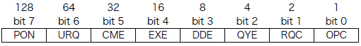
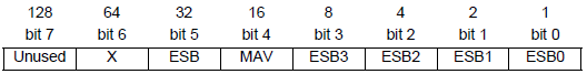
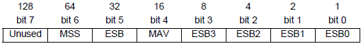
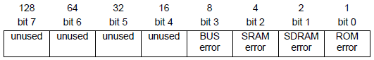
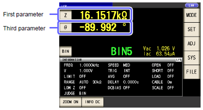
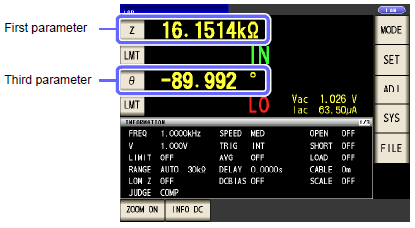
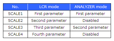
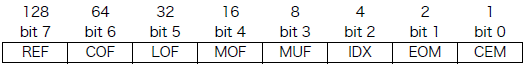
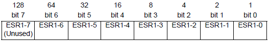
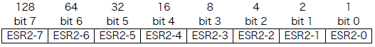
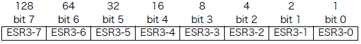
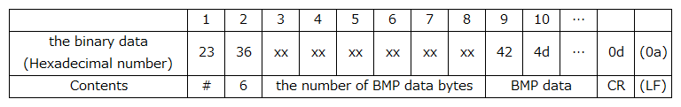
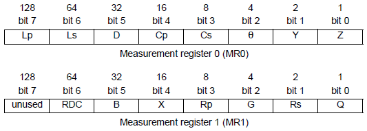
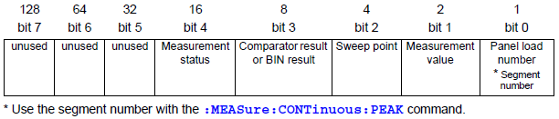
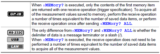
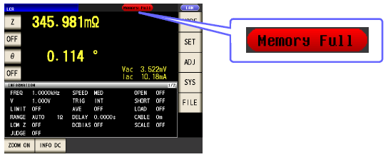
 " is saved.