Product Mar. 29, 2024
Discovering the Future of EV and PV Inverter Development through New Power Analyzer Functions
Hioki is pleased to announce a significant update to the firmware of its flagship power analyzer series, the PW8001. This update aims to further contribute to the development of Electric Vehicle (EV) and Photovoltaic (PV) inverters. The three main noteworthy features include Power Spectrum Analysis (PSA) (*1), IEC standard-compliant power quality measurements, and an optical link interface for multi-unit synchronization. These features have been implemented in the power analyzers to shape the future of inverter development. Users who already own PW8001 series devices can update their firmware for free. By contributing to the e-mobility and renewable energy markets, Hioki is promoting the reduction of greenhouse gas emissions.
- *1:PSA (Power Spectrum Analysis): A function for frequency analysis of power. PSA allows isolation and observation of inverter output power at intended frequencies as well as unintended high-frequency power caused by noise.
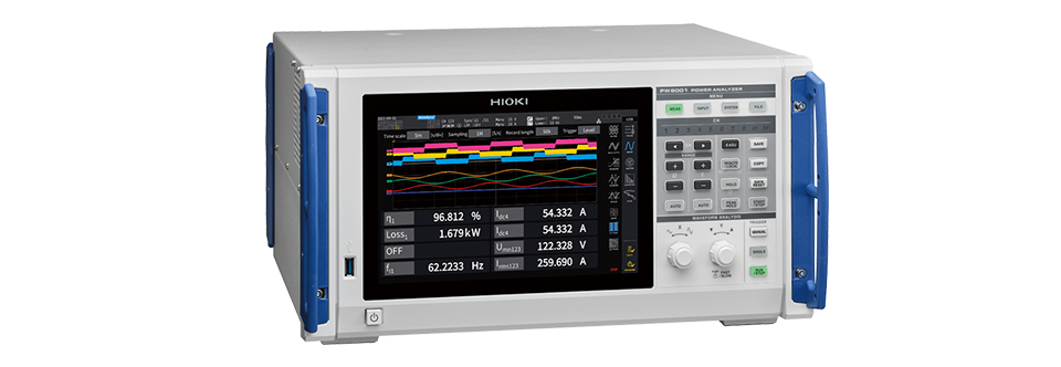
Power Analyzer PW8001 series
Development background
Reducing greenhouse gas emissions has become a driving force behind global EV and PV development. Inverters play a critical role in these areas by converting electrical power.
In the context of EV development, energy consumption has a significant impact on driving range. EV inverters convert the DC power from the battery into AC power for motor rotation. However, power losses occur inside inverters during conversion. To extend the driving range, minimizing power loss in EV inverters is essential. Detailed power analysis is necessary to identify the causes of losses and demonstrate the effectiveness of improvements.
Solar or PV panels can generate electricity with a lower environmental impact than fossil fuels. That said, the sunlight needed by PV panels is an unstable source of energy. PV inverters are designed so that fluctuations in output caused by abrupt weather changes do not adversely affect the power grid. PV inverters convert DC power from PV panels into AC power that can be supplied to the grid. To prevent output fluctuations from negatively impacting the power grid, many countries require PV inverters to undergo certification tests based on standards and regulations.
Hioki has supplied its PW8001 series power analyzers featuring world-class measurement accuracy for use in inverter development. This update will further advance the development of state-of-the-art EV and PV inverters. Hioki will continue to help reduce greenhouse gas emissions by supporting development of low-energy-consumption inverters.
New functions and features
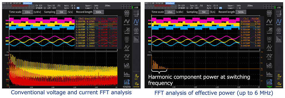
Frequency analysis of losses using PSA (Power Spectrum Analysis)
Inverters contain electrical circuitry for converting DC current to AC current. Switching circuits using PWM (*2) and boost chopper circuits of DC-DC converters (*3) cause power loss due to high-frequency noise. Frequency analysis of high-frequency power is one technique for assessing what causes such losses. The frequency analysis of the PW8001 series has been enhanced to analyze not only voltage and current but also power. PSA makes it possible to isolate power losses in the high-frequency domain.
- *2:PWM (pulse width modulation): Technology for converting DC current into AC current. A semiconductor switching circuit generates AC current by adjusting its “on” and “off” times.
- *3:DC-DC converter: A device that converts DC levels to match the specifications of electrical equipment. Internally, such devices use a semiconductor switching circuit.
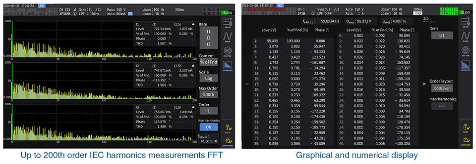
Compliance with IEC measurement standards for PV inverters
Many countries have adopted standards defining certification testing for PV inverters. Many of these tests require complex calculations for harmonics, interharmonics (*4), and flicker (*5) based on IEC measurement standards. Harmonic measurement compliant with standards can be made by selecting IEC harmonic mode, a new addition to the PW8001 series.
- *4:Harmonics and interharmonics: A type of noise contained in AC voltage and current. They cause energy losses and, in the worst case, may lead to equipment failure or fire. Therefore, it must be limited in inverter output.
- *5:Flicker: Minuscule, intermittent fluctuations in an AC voltage. The phenomenon causes lights to flicker.
Optical link interface(*6) for making simultaneous measurements of multiple inverters
MPPT (*7) is a control method for solar power generation. Since MPPT inverters are used to control multiple panels (or strings of panels), evaluating the inverter also requires simultaneous measurement of many channels. The optical link interface allows two PW8001 series units to be connected, enabling simultaneous power measurement of up to 16 channels. Using this approach to create integrated data reduces the workload associated with after-the-fact manipulation of measurement data by inverter developers.
- *6:Available only in the PW8001-04, PW8001-05, PW8001-06, PW8001-14, PW8001-15, and PW8001-16.
- *7:MPPT (Maximum Power Point Tracking): One of the control methods for solar inverters. It controls circuits to maximize energy generation based on the output characteristics of solar panels and the amount of sunlight.
Main applications
The newly added functions provide new value to power analyzer customers in the markets of e-mobility, solar power, and other inverters for the following applications:
Investigation of Inverter Motor Loss Using the Power Spectrum Analysis (PSA) Function
Evaluation of Efficiency in the Development of Multi-input MPPT Inverters
Addressing EMC Noise Early On: IEC Harmonics, Voltage-Fluctuations/Flicker, and High-Frequency Noise
Links
POWER ANALYZER PW8001 Ver. 2.0: New Features
POWER ANALYZER PW8001: Product page
Product lineup
The PW8001 series has a lineup of 12 models with different factory-installed features. Six of these models (*8) are newly being released with the addition of the optical link interface function.
All 12 models support PSA (power spectrum analysis) and IEC harmonic mode.
- *8:PW8001-04、PW8001-05、PW8001-06、PW8001-14、PW8001-15、PW8001-16
| Model No. | Factory-installed options |
|---|---|
| PW8001-01 | No options |
| PW8001-02 | Waveform and D/A output |
| PW8001-03 | CAN or CAN FD Interface |
| PW8001-04 | Optical link interface |
| PW8001-05 | Waveform and D/A output, Optical link interface |
| PW8001-06 | CAN or CAN FD Interface, Optical link interface |
| PW8001-11 | Motor analysis |
| PW8001-12 | Motor analysis, Waveform and D/A output |
| PW8001-13 | Motor analysis, CAN or CAN FD Interface |
| PW8001-14 | Motor analysis, Optical link interface |
| PW8001-15 | Motor analysis, Waveform and D/A output, Optical link interface |
| PW8001-16 | Motor analysis, CAN or CAN FD Interface, Optical link interface |
Contact us
For inquiries such as quotes, demonstrations, and trial usage, please use Hioki’s contact form for a personalized reply from your closest or most appropriate Hioki representative.
- The information provided is current as of the date of publishing.
- Please note that prices, specifications, and other information contained in this texts are subject to change without notice.
- The company names and product names used in this text are registered trademarks or trademarks of their respective companies.
About HIOKI
Established in 1935, HIOKI E.E. CORPORATION (TSE: 6866) has grown to become a world leader in providing consistent delivery of test and measuring instruments through advanced design, manufacturing, and sales and services. By offering over 200 main products characterized by safety and quality while meeting an expansive range of applications, we aim to contribute to the efficiency and value of our customers' work in research and development, production and electrical maintenance. Hioki products and services are available around the world through our extensive network of subsidiaries and distributors. For more information, visit us at www.hioki.com.