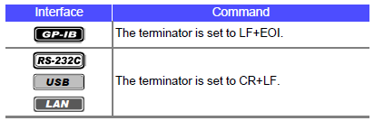
Syntax |
Command |
*CLS |
Query |
|
|
Response |
|
|
Parameter |
|
|
Explanation |
Command |
Clears the content of the event registers (SESR, ESR0, ESR1, ESR2, ESR3). |
Query |
|
|
Example |
Command |
*CLS |
Query |
|
|
Response |
|
|
Note |
GPIB:The output queue is unaffected. |
Syntax |
Command |
*ESE <Mask value> |
Query |
*ESE? |
|
Response |
<Mask value> |
|
Parameter |
<Mask value> = 0 to 255 (NR1) |
|
Explanation |
Command |
Sets the mask pattern of SESER. |
Query |
Returns the mask pattern of SESER. |
|
Example |
Command |
*ESE 36 |
Query |
*ESE? |
|
Response |
*ESE 36
(when HEADER ON) |
|
Note |
|
Syntax |
Command |
|
Query |
*ESR? |
|
Response |
<Register value> |
|
Parameter |
<Register value> = 0 to 255 (NR1) |
|
Explanation |
Command |
|
Query |
Returns the register value of SESR, and clears the register. |
|
Example |
Command |
|
Query |
*ESR? |
|
Response |
32
|
|
Note |
Bit 6 and 1 are not used in the instrument. |
Syntax |
Command |
|
Query |
*IDN? |
|
Response |
<Maker Name>,<Serial No.>,< Model Name>,<Software Version> |
|
Parameter |
|
|
Explanation |
Command |
|
Query |
Returns the ID of the instrument. |
|
Example |
Command |
|
Query |
*IDN? |
|
Response |
HIOKI,IM3536,123456789,V1.00
|
|
Note |
|
Syntax |
Command |
*OPC |
Query |
|
|
Response |
|
|
Parameter |
|
|
Explanation |
Command |
Sets the OPC (bit 0) of the SESR (standard event status register) at the point in time that command processing finishes for the sent commands which are before the command. |
Query |
|
|
Example |
Command |
A;B;*OPC;C |
Query |
|
|
Response |
|
|
Note |
|
Syntax |
Command |
|
Query |
*OPC? |
|
Response |
|
|
Parameter |
|
|
Explanation |
Command |
|
Query |
Sends the response of ASCII 1 at the point in time that command processing finishes for the sent commands which are before the *OPC command. A header is not added to the response message. |
|
Example |
Command |
|
Query |
*OPC? |
|
Response |
1
|
|
Note |
|
Syntax |
Command |
*RST |
Query |
|
|
Response |
|
|
Parameter |
|
|
Explanation |
Command |
Initializes the instrument. |
Query |
|
|
Example |
Command |
*RST |
Query |
|
|
Response |
|
|
Note |
When the instrument is initialized, the current setting information is deleted and the |
Syntax |
Command |
*SRE <Mask value> |
Query |
*SRE? |
|
Response |
<Mask value> |
|
Parameter |
<Mask value> = 0 to 255 (NR1) |
|
Explanation |
Command |
Sets the mask pattern of SRER. |
Query |
Returns the mask pattern of SRER. |
|
Example |
Command |
*SRE 34 |
Query |
*SRE? |
|
Response |
*SRE 34
(when HEADER ON) |
|
Note |
|
Syntax |
Command |
|
Query |
*STB? |
|
Response |
<Register value> |
|
Parameter |
<Register value> = 0 to 255 (NR1) |
|
Explanation |
Command |
|
Query |
Returns the register value of STB. |
|
Example |
Command |
|
Query |
*STB? |
|
Response |
8
|
|
Note |
|
Syntax |
Command |
*TRG |
Query |
|
|
Response |
|
|
Parameter |
|
|
Explanation |
Command |
Performs sampling once when there is an external trigger. |
Query |
|
|
Example |
Command |
:TRIGger EXTernal;*TRG;:MEASure? |
Query |
|
|
Response |
|
|
Note |
An execution error occurs if this command is executed when there is an internal trigger. |
Syntax |
Command |
|
Query |
*TST? |
|
Response |
<Result> |
|
Parameter |
<Result> = 0 to 15 (NR1) |
|
Explanation |
Command |
|
Query |
Executes the following self tests and returns the result.
The tests take approximately 1 minute. Do not send commands or turn off the power of the instrument during the tests. A header is not added to the response message. |
|
Example |
Command |
|
Query |
*TST? |
|
Response |
5
|
|
Note |
If the result is other than 0, the instrument may have malfunctioned. |
Syntax |
Command |
*WAI |
Query |
|
|
Response |
|
|
Parameter |
|
|
Explanation |
Command |
Executes the command following *WAI after command processing is finished. |
Query |
|
|
Example |
Command |
A;B;*WAI;C
:FREQuency 120;:MEASure? In this case, it is not certain which frequency measurement value will be sent in response to the :MEASure? query.
:FREQuency 120;*WAI;:MEASure? In this case, the 120 Hz frequency measurement value is sent in response to the :MEASure? query. |
Query |
|
|
Response |
|
|
Note |
Unique commands other than the ":MEASure?" query use sequential commands. |
Syntax |
Command |
:ESE0 <Mask value> |
Query |
:ESE0? |
|
Response |
<Mask value> |
|
Parameter |
<Mask value> = 0 to 255 (NR1) |
|
Explanation |
Command |
Sets the mask pattern of ESER0. |
Query |
Returns the mask pattern of ESER0. |
|
Example |
Command |
:ESE0 20 |
Query |
:ESE0? |
|
Response |
:ESE0 20
(when HEADER ON) |
|
Note |
This register's bits are reset after 1 measurement completes. |
Syntax |
Command |
:ESE1 <Mask value> |
Query |
:ESE1? |
|
Response |
<Mask value> |
|
Parameter |
<Mask value> = 0 to 255 (NR1) |
|
Explanation |
Command |
Sets the mask pattern of ESER1. |
Query |
Returns the mask pattern of ESER1. |
|
Example |
Command |
:ESE1 64 |
Query |
:ESE1? |
|
Response |
:ESE1 64
(when HEADER ON) |
|
Note |
For details on each of the bits, refer to "About Event Registers". |
Syntax |
Command |
:ESE2 <Mask value> |
Query |
:ESE2? |
|
Response |
<Mask value> |
|
Parameter |
<Mask value> = 0 to 255 (NR1) |
|
Explanation |
Command |
Sets the mask pattern of ESER2. |
Query |
Returns the mask pattern of ESER2. |
|
Example |
Command |
:ESE2 1 |
Query |
:ESE2? |
|
Response |
:ESE2 1
(when HEADER ON) |
|
Note |
For details on each of the bits, refer to "About Event Registers". |
Syntax |
Command |
:ESE3 <Mask value> |
Query |
:ESE3? |
|
Response |
<Mask value> |
|
Parameter |
<Mask value> = 0 to 255 (NR1) |
|
Explanation |
Command |
Sets the mask pattern of ESER3. |
Query |
Returns the mask pattern of ESER3. |
|
Example |
Command |
:ESE3 3 |
Query |
:ESE3? |
|
Response |
:ESE3 3
(when HEADER ON) |
|
Note |
For details on each of the bits, refer to "About Event Registers". |
Syntax |
Command |
|
Query |
:ESR0? |
|
Response |
<Register value> |
|
Parameter |
<Register value> = 0 to 255 (NR1) |
|
Explanation |
Command |
|
Query |
Returns the register value of event status register 0 (ESR0), and clears the register. |
|
Example |
Command |
|
Query |
:ESR0? |
|
Response |
4
|
|
Note |
This register's bits are reset after 1 measurement completes. |
Syntax |
Command |
|
Query |
:ESR1? |
|
Response |
<Register value> |
|
Parameter |
<Register value> = 0 to 255 (NR1) |
|
Explanation |
Command |
|
Query |
Returns the register value of event status register 1 (ESR1), and clears the register. |
|
Example |
Command |
|
Query |
:ESR1? |
|
Response |
82
|
|
Note |
When comparator measurement is performed in LCR mode, the bits are set after one measurement finishes. |
Syntax |
Command |
|
Query |
:ESR2? |
|
Response |
<Register value> |
|
Parameter |
<Register value> = 0 to 255 (NR1) |
|
Explanation |
Command |
|
Query |
Returns the register value of event status register 2 (ESR2), and clears the register. |
|
Example |
Command |
|
Query |
:ESR2? |
|
Response |
1
|
|
Note |
When BIN measurement is performed in LCR mode, the bits are set after one measurement finishes. |
Syntax |
Command |
|
Query |
:ESR3? |
|
Response |
<Register value> |
|
Parameter |
<Register value> = 0 to 255 (NR1) |
|
Explanation |
Command |
|
Query |
Returns the register value of event status register 3 (ESR3), and clears the register. |
|
Example |
Command |
|
Query |
:ESR3? |
|
Response |
64
|
|
Note |
When BIN measurement is performed in LCR mode, the bits are set after one measurement finishes. |
Syntax |
Command |
:MODE <LCR/CONTinuous> |
Query |
:MODE? |
|
Response |
<LCR/CONTINUOUS> |
|
Parameter |
|
|
Explanation |
Command |
Sets measurement mode. LCR : Sets measurement mode to LCR mode. |
Query |
Returns the setting of measurement mode. |
|
Example |
Command |
:MODE LCR |
Query |
:MODE? |
|
Response |
:MODE LCR
(when HEADER ON) |
|
Note |
|
Syntax |
Command |
:FREQuency <Frequency> |
Query |
:FREQuency? |
|
Response |
<Frequency> |
|
Parameter |
<Frequency> = 4.00 to 8.0000E+06 (NR3) |
|
Explanation |
Command |
Sets the measurement frequency. |
Query |
Returns the setting of the measurement frequency. |
|
Example |
Command |
:FREQuency 1000 |
Query |
:FREQuency? |
|
Response |
:FREQUENCY 1.0000E+03
(when HEADER ON) |
|
Note |
|
Syntax |
Command |
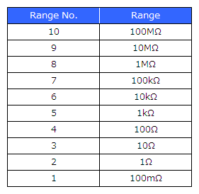
:RANGe <Range No.> |
Query |
:RANGe? |
|
Response |
<Range No.> |
|
Parameter |
<Range No.> = 1 to 10 (NR1) |
|
Explanation |
Command |
Sets the measurement range. |
Query |
Returns the measurement range. |
|
Example |
Command |
:RANGe 4 |
Query |
:RANGe? |
|
Response |
:RANGE 4
(when HEADER ON) |
|
Note |
|
Syntax |
Command |
:RANGe:AUTO <ON/OFF> |
Query |
:RANGe:AUTO? |
|
Response |
<ON/OFF> |
|
Parameter |
|
|
Explanation |
Command |
Sets the measurement range to be changed automatically. ON: The range is changed automatically by the auto ranging function. |
Query |
Returns the automatic setting of the measurement range. |
|
Example |
Command |
:RANGe:AUTO ON |
Query |
:RANGe:AUTO? |
|
Response |
:RANGE:AUTO ON
(when HEADER ON) |
|
Note |
|
Syntax |
Command |
:RANGe:AUTO:LIMit <RST/lower limit range>,<upper limit range> |
Query |
:RANGe:AUTO:LIMit? |
|
Response |
<lower limit range>,<upper limit range> |
|
Parameter |
<lower limit range> = 1 to 10 (NR1) |
|
Explanation |
Command |
Sets the AUTO range limit function. |
Query |
Returns the setting of the AUTO range limit function. |
|
Example |
Command |
:RANGe:AUTO:LIMit 4,7 |
Query |
:RANGe:AUTO:LIMit? |
|
Response |
:RANGE:AUTO:LIMIT 4,7
(when HEADER ON) |
|
Note |
The setting is reset by issuing ": RANGe:AUTO:LIMit RST". |
Syntax |
Command |
:RANGe:JSYNc <ON/OFF> |
Query |
:RANGe:JSYNc? |
|
Response |
<ON/OFF> |
|
Parameter |
|
|
Explanation |
Command |
Sets the JUDGE synchronization function. |
Query |
Returns the setting of the JUDGE synchronization. |
|
Example |
Command |
:RANGe:JSYNc ON |
Query |
:RANGe:JSYNc? |
|
Response |
:RANGE:JSYNC ON
(when HEADER ON) |
|
Note |
|
Syntax |
Command |
:RANGe:LOWZ <ON/OFF> |
Query |
:RANGe:LOWZ? |
|
Response |
<ON/OFF> |
|
Parameter |
|
|
Explanation |
Command |
Sets low Z high accuracy mode. |
Query |
Returns the setting of low Z high accuracy mode. |
|
Example |
Command |
:RANGe:LOWZ ON |
Query |
:RANGe:LOWZ? |
|
Response |
:RANGE:LOWZ ON
(when HEADER ON) |
|
Note |
|
Syntax |
Command |
:RANGe:SYNC <ON/OFF> |
Query |
:RANGe:SYNC? |
|
Response |
<ON/OFF> |
|
Parameter |
|
|
Explanation |
Command |
Sets the range synchronization function. |
Query |
Returns the setting of the range synchronization function. |
|
Example |
Command |
:RANGe:SYNC ON |
Query |
:RANGe:SYNC? |
|
Response |
:RANGE:SYNC ON
(when HEADER ON) |
|
Note |
|
Syntax |
Command |
:RANGe:SYNC:AVERaging <ALL/Range No.>,<OFF/number of averaging times> |
Query |
:RANGe:SYNC:AVERaging? <Range No.> |
|
Response |
<OFF/number of averaging times> |
|
Parameter |
<Range No.> = 1 to 10 (NR1) |
|
Explanation |
Command |
Sets the number of measurement averaging times for the range synchronization function. OFF: Disables the averaging function. |
Query |
Returns the number of measurement averaging times for the range synchronization function. |
|
Example |
Command |
:RANGe:SYNC:AVERaging 4,32 |
Query |
:RANGe:SYNC:AVERaging? 4 |
|
Response |
:RANGE:SYNC:AVERAGING 32
(when HEADER ON) |
|
Note |
When ALL is set, this is reflected to all ranges. |
Syntax |
Command |
:RANGe:SYNC:SPEEd <ALL/Range No.>,<FAST/MEDium/SLOW/SLOW2> |
Query |
:RANGe:SYNC:SPEEd? <Range No.> |
|
Response |
<FAST/MEDIUM/SLOW/SLOW2> |
|
Parameter |
<Range No.> = 1 to 10 (NR1) |
|
Explanation |
Command |
Sets the measurement speed for the range synchronization function. |
Query |
Returns the measurement speed for the range synchronization function. |
|
Example |
Command |
:RANGe:SYNC:SPEEd 4,FAST |
Query |
:RANGe:SYNC:SPEEd? 4 |
|
Response |
:RANGE:SYNC:SPEED FAST
(when HEADER ON) |
|
Note |
When ALL is set, this is reflected to all ranges. |
Syntax |
Command |
:RANGe:SYNC:TRIGger:DELay <ALL/Range No.>,<Trigger delay time> |
Query |
:RANGe:SYNC:TRIGger:DELay? <Range No.> |
|
Response |
<Trigger delay time> |
|
Parameter |
<Range No.> = 1 to 10 (NR1) |
|
Explanation |
Command |
Sets the trigger delay time for the range synchronization function. |
Query |
Returns the setting of the trigger delay time for the range synchronization function. |
|
Example |
Command |
:RANGe:SYNC:TRIGger:DELay 4,0.1 |
Query |
:RANGe:SYNC:TRIGger:DELay? 4 |
|
Response |
:RANGE:SYNC:TRIGGER:DELAY 0.1000
(when HEADER ON) |
|
Note |
When ALL is set, this is reflected to all ranges. |
Syntax |
Command |
:RANGe:SYNC:SSOurce <ALL/Range No.>,<ON/OFF> |
Query |
:RANGe:SYNC:SSOurce? <Range No.> |
|
Response |
<ON/OFF> |
|
Parameter |
<Range No.> = 1 to 10 (NR1) |
|
Explanation |
Command |
Enables/disables the trigger synchronous output function for the range synchronization function. ON: Enables the trigger synchronous output function. |
Query |
Returns the setting of the trigger synchronous output function for the range synchronization function. |
|
Example |
Command |
:RANGe:SYNC:SSOurce 4,ON |
Query |
:RANGe:SYNC:SSOurce? 4 |
|
Response |
:RANGE:SYNC:SSOURCE ON
(when HEADER ON) |
|
Note |
When ALL is set, this is reflected to all ranges. |
Syntax |
Command |
:RANGe:SYNC:SSOurce:WAIT <ALL/Range No.>,<Wait time> |
Query |
:RANGe:SYNC:SSOurce:WAIT? <Range No.> |
|
Response |
<Wait time> |
|
Parameter |
<Range No.> = 1 to 10 (NR1) |
|
Explanation |
Command |
Sets the wait time for the period from after the measurement signal is output by applying a trigger for the range synchronization function until measurement starts. |
Query |
Returns the wait time of the trigger synchronous output function for the range synchronization function. |
|
Example |
Command |
:RANGe:SYNC:SSOurce:WAIT 4,0.5000 |
Query |
:RANGe:SYNC:SSOurce:WAIT? 4 |
|
Response |
:RANGE:SYNC:SSOURCE:WAIT 0.5000
|
|
Note |
When ALL is set, this is reflected to all ranges. |
Syntax |
Command |
:LEVel <V/CV/CC> |
Query |
:LEVel? |
|
Response |
<V/CV/CC> |
|
Parameter |
|
|
Explanation |
Command |
Sets the measurement signal type to any one of open-circuit voltage, constant voltage, and constant current. V: Sets open-circuit voltage. |
Query |
Returns the measurement signal type. |
|
Example |
Command |
:LEVel V |
Query |
:LEVel? |
|
Response |
:LEVEL V
(when HEADER ON) |
|
Note |
|
Syntax |
Command |
:LEVel:CCURRent <Constant current level> |
Query |
:LEVel:CCURRent? |
|
Response |
<Constant current level> |
|
Parameter |
<Constant current level> = The settable range varies depending on the conditions. (NR3) |
|
Explanation |
Command |
Sets the constant current level. |
Query |
Returns the currently set constant current level. |
|
Example |
Command |
:LEVel:CCURRent 10E-3 |
Query |
:LEVel:CCURRent? |
|
Response |
:LEVEL:CCURRENT 10.00E-03
(when HEADER ON) |
|
Note |
|
Syntax |
Command |
:LEVel:CVOLTage <Constant voltage level> |
Query |
:LEVel:CVOLTage? |
|
Response |
<Constant voltage level> |
|
Parameter |
<Constant voltage level> = The settable range varies depending on the conditions. (NR3) |
|
Explanation |
Command |
Sets the constant voltage level. |
Query |
Returns the currently set constant voltage level. |
|
Example |
Command |
:LEVel:CVOLTage 1.000 |
Query |
:LEVel:CVOLTage? |
|
Response |
:LEVEL:CVOLTAGE 1.000
(when HEADER ON) |
|
Note |
|
Syntax |
Command |
:LEVel:VOLTage <Open-circuit voltage level> |
Query |
:LEVel:VOLTage? |
|
Response |
<Open-circuit voltage level> |
|
Parameter |
<Open-circuit voltage level> = The settable range varies depending on the conditions. (NR3) |
|
Explanation |
Command |
Sets the open-circuit voltage level. |
Query |
Returns the currently set open-circuit voltage level. |
|
Example |
Command |
:LEVel:VOLTage 1.000 |
Query |
:LEVel:VOLTage? |
|
Response |
:LEVEL:VOLTAGE 1.000
(when HEADER ON) |
|
Note |
|
Syntax |
Command |
:SPEEd <FAST/MEDium/SLOW/SLOW2> |
Query |
:SPEEd? |
|
Response |
<FAST/MEDIUM/SLOW/SLOW2> |
|
Parameter |
|
|
Explanation |
Command |
Sets the measurement speed. |
Query |
Returns the setting of the measurement speed. |
|
Example |
Command |
:SPEEd MEDium |
Query |
:SPEEd? |
|
Response |
:SPEED MEDIUM
(when HEADER ON) |
|
Note |
|
Syntax |
Command |
:LIMiter <ON/OFF> |
Query |
:LIMiter? |
|
Response |
<ON/OFF> |
|
Parameter |
|
|
Explanation |
Command |
Sets the limit function. |
Query |
Returns the setting of the limit function. |
|
Example |
Command |
:LIMiter ON |
Query |
:LIMiter? |
|
Response |
:LIMITER ON
(when HEADER ON) |
|
Note |
|
Syntax |
Command |
:LIMiter:CURRent <Current limit value> |
Query |
:LIMiter:CURRent? |
|
Response |
<Current limit value> |
|
Parameter |
<Current limit value> = 0.01 m to 100.00 mA (NR3) |
|
Explanation |
Command |
Sets the current limit value. |
Query |
Returns the current limit value. |
|
Example |
Command |
:LIMiter:CURRent 50.00E-03 |
Query |
:LIMiter:CURRent? |
|
Response |
:LIMITER:CURRENT 50.00E-03
(when HEADER ON) |
|
Note |
|
Syntax |
Command |
:LIMiter:VOLTage <Voltage limit value> |
Query |
:LIMiter:VOLTage? |
|
Response |
<Voltage limit value> |
|
Parameter |
<Voltage limit value> = 0.01 to 5.000 V (NR3) |
|
Explanation |
Command |
Sets the voltage limit value. |
Query |
Returns the voltage limit value. |
|
Example |
Command |
:LIMiter:VOLTage 5.000 |
Query |
:LIMiter:VOLTage? |
|
Response |
:LIMITER:VOLTAGE 5.000
(when HEADER ON) |
|
Note |
|
Syntax |
Command |
:AVERaging <OFF/ number of averaging times> |
Query |
:AVERaging? |
|
Response |
<OFF/ number of averaging times> |
|
Parameter |
<number of averaging times> = 1 to 256 (NR1) |
|
Explanation |
Command |
Sets the number of averaging times. OFF: Disables the averaging function. |
Query |
Returns the number of measurement averaging times. |
|
Example |
Command |
:AVERaging 32 |
Query |
:AVERaging? |
|
Response |
:AVERAGING 32
(when HEADER ON) |
|
Note |
Setting the number of averaging times to 1 automatically sets the averaging function to OFF. |
Syntax |
Command |
:DCBias <ON/OFF> |
Query |
:DCBias? |
|
Response |
<ON/OFF> |
|
Parameter |
|
|
Explanation |
Command |
Sets the DC bias function. |
Query |
Returns the setting of the DC bias function. |
|
Example |
Command |
:DCBias ON |
Query |
:DCBias? |
|
Response |
:DCBIAS ON
(when HEADER ON) |
|
Note |
|
Syntax |
Command |
:DCBias:LEVel <DC bias level> |
Query |
:DCBias:LEVel? |
|
Response |
<DC bias level> |
|
Parameter |
<DC bias level> = 0.00 to 2.50 V (NR2) |
|
Explanation |
Command |
Sets the DC bias level. |
Query |
Returns the DC bias level. |
|
Example |
Command |
:DCBias:LEVel 1.50 |
Query |
:DCBias:LEVel? |
|
Response |
:DCBIAS:LEVEL 1.50
(when HEADER ON) |
|
Note |
|
Syntax |
Command |
:TRIGger <INTernal/EXTernal> |
Query |
:TRIGger? |
|
Response |
<INTERNAL/EXTERNAL> |
|
Parameter |
|
|
Explanation |
Command |
Sets the trigger mode. INTernal: Sets the internal trigger. |
Query |
Returns the setting of the trigger mode. |
|
Example |
Command |
:TRIGger INTernal |
Query |
:TRIGger? |
|
Response |
:TRIGGER INTERNAL
(when HEADER ON) |
|
Note |
|
Syntax |
Command |
:TRIGger:DELay <Trigger delay time> |
Query |
:TRIGger:DELay? |
|
Response |
<Trigger delay time> |
|
Parameter |
<Trigger delay time> = 0 to 9.9999 s (NR2) |
|
Explanation |
Command |
Sets the trigger delay time. |
Query |
Returns the setting of the trigger delay time. |
|
Example |
Command |
:TRIGger:DELay 0.1 |
Query |
:TRIGger:DELay? |
|
Response |
:TRIGGER:DELAY 0.1000
(when HEADER ON) |
|
Note |
To set the trigger delay function to OFF, set |
Syntax |
Command |
:SSOurce <ON/OFF> |
Query |
:SSOurce? |
|
Response |
<ON/OFF> |
|
Parameter |
|
|
Explanation |
Command |
Enables or disables the trigger synchronous output function. ON: Enables the trigger synchronous output function. |
Query |
Returns the setting of the trigger synchronous output function. |
|
Example |
Command |
:SSOurce ON |
Query |
:SSOurce? |
|
Response |
:SSOURCE ON
(when HEADER ON) |
|
Note |
|
Syntax |
Command |
:SSOurce:WAIT <Wait time> |
Query |
:SSOurce:WAIT? |
|
Response |
<Wait time> |
|
Parameter |
<Trigger delay time> = 0.0010 to 9.9999 s (NR2) |
|
Explanation |
Command |
Sets the wait time for the period from after the measurement signal is output by applying a trigger until measurement starts. |
Query |
Returns the wait time of the trigger synchronous output function. |
|
Example |
Command |
:SSOurce:WAIT 0.5000 |
Query |
:SSOurce:WAIT? |
|
Response |
:SSOURCE:WAIT 0.5000
(when HEADER ON) |
|
Note |
A short wait time may result in an increase in measurement errors. |
Syntax |
Command |
:DCResistance:RANGe <Range No.> |
Query |
:DCResistance:RANGe? |
|
Response |
<Range No.> |
|
Parameter |
<Range No.> = 1 to 10 (NR1) |
|
Explanation |
Command |
Sets the measurement range for when DC resistance measurement. |
Query |
Returns the measurement range for when DC resistance measurement. |
|
Example |
Command |
:DCResistance:RANGe 4 |
Query |
:DCResistance:RANGe? |
|
Response |
:DCRESISTANCE:RANGE 4
(when HEADER ON) |
|
Note |
|
Syntax |
Command |
:DCResistance:RANGe:AUTO <ON/OFF> |
Query |
:DCResistance:RANGe:AUTO? |
|
Response |
<ON/OFF> |
|
Parameter |
|
|
Explanation |
Command |
Sets the measurement range for when DC resistance measurement to be changed automatically. ON: The range is changed automatically by the auto ranging function. |
Query |
Returns the automatic setting of the measurement range for when DC resistance measurement. |
|
Example |
Command |
:DCResistance:RANGe:AUTO ON |
Query |
:DCResistance:RANGe:AUTO? |
|
Response |
:DCRESISTANCE:RANGE:AUTO ON
(when HEADER ON) |
|
Note |
|
Syntax |
Command |
:DCResistance:RANGe:AUTO:LIMit <RST/lower limit range>,<upper limit range> |
Query |
:DCResistance:RANGe:AUTO:LIMit? |
|
Response |
<lower limit range>,<upper limit range> |
|
Parameter |
<lower limit range> = 1 to 10 (NR1) |
|
Explanation |
Command |
Sets the AUTO range limit function during DC resistance measurement. |
Query |
Returns the AUTO range limit function during DC resistance measurement. |
|
Example |
Command |
:DCResistance:RANGe:AUTO:LIMit 4,7 |
Query |
:DCResistance:RANGe:AUTO:LIMit? |
|
Response |
:DCRESISTANCE:RANGE:AUTO:LIMIT 4,7
(when HEADER ON) |
|
Note |
The setting is reset by issuing ":DCResistance:RANGe:AUTO:LIMit RST". |
Syntax |
Command |
:DCResistance:RANGe:LOWZ <ON/OFF> |
Query |
:DCResistance:RANGe:LOWZ? |
|
Response |
<ON/OFF> |
|
Parameter |
|
|
Explanation |
Command |
Sets low Z high accuracy mode for when DC resistance measurement. |
Query |
Returns the setting of low Z high accuracy mode for when DC resistance measurement. |
|
Example |
Command |
:DCResistance:RANGe:LOWZ ON |
Query |
:DCResistance:RANGe:LOWZ? |
|
Response |
:DCRESISTANCE:RANGE:LOWZ ON
(when HEADER ON) |
|
Note |
|
Syntax |
Command |
:DCResistance:RANGe:JSYNc <ON/OFF> |
Query |
:DCResistance:RANGe:JSYNc? |
|
Response |
<ON/OFF> |
|
Parameter |
|
|
Explanation |
Command |
Sets the JUDGE synchronization setting during DC resistance measurement. |
Query |
Returns the setting of the JUDGE synchronization during DC resistance measurement. |
|
Example |
Command |
:DCResistance:RANGe:JSYNc ON |
Query |
:DCResistance:RANGe:JSYNc? |
|
Response |
:DCRESISTANCE:RANGE:JSYNC ON
(when HEADER ON) |
|
Note |
|
Syntax |
Command |
:DCResistance:RANGe:SYNC:AVERaging <ALL/Range No.>,<OFF/number of averaging times> |
Query |
:DCResistance:RANGe:SYNC:AVERaging? <Range No.> |
|
Response |
<ALL/Range No.>,<OFF/number of averaging times> |
|
Parameter |
<Range No.> = 1 to 10 (NR1) |
|
Explanation |
Command |
Sets the number of measurement averaging times for the range synchronization function during DC resistance measurement. OFF: Disables the averaging function. |
Query |
Returns the number of measurement averaging times for the range synchronization function during DC resistance measurement. |
|
Example |
Command |
:DCResistance:RANGe:SYNC:AVERaging 4,32 |
Query |
:DCResistance:RANGe:SYNC:AVERaging? 4 |
|
Response |
:DCRESISTANCE:RANGE:SYNC:AVERAGING 32
(when HEADER ON) |
|
Note |
When ALL is set, this is reflected to all ranges. |
Syntax |
Command |
:DCResistance:RANGe:SYNC:SPEEd <ALL/Range No.>,<FAST/MEDium/SLOW/SLOW2> |
Query |
:DCResistance:RANGe:SYNC:SPEEd? <Range No.> |
|
Response |
<ALL/Range No.>,<FAST/MEDium/SLOW/SLOW2> |
|
Parameter |
<Range No.> = 1 to 10 (NR1) |
|
Explanation |
Command |
Sets the measurement speed for the range synchronization function during DC resistance measurement. |
Query |
Returns the measurement speed for the range synchronization function during DC resistance measurement. |
|
Example |
Command |
:DCResistance:RANGe:SYNC:SPEEd 4,FAST |
Query |
:DCResistance:RANGe:SYNC:SPEEd? 4 |
|
Response |
:DCRESISTANCE:RANGE:SYNC:SPEED FAST
(when HEADER ON) |
|
Note |
When ALL is set, this is reflected to all ranges. |
Syntax |
Command |
:DCResistance:SPEEd <FAST/MEDium/SLOW/SLOW2> |
Query |
:DCResistance:SPEEd? |
|
Response |
<FAST/MEDIUM/SLOW/SLOW2> |
|
Parameter |
|
|
Explanation |
Command |
Sets the measurement speed for when DC resistance measurement. |
Query |
Returns the setting of the measurement speed for when DC resistance measurement. |
|
Example |
Command |
:DCResistance:SPEEd MEDium |
Query |
:DCResistance:SPEEd? |
|
Response |
:DCRESISTANCE:SPEED MEDIUM
(when HEADER ON) |
|
Note |
|
Syntax |
Command |
:DCResistance:AVERaging <OFF/ number of averaging times> |
Query |
:DCResistance:AVERaging? |
|
Response |
<OFF/ number of averaging times> |
|
Parameter |
<number of averaging times> = 1 to 256 (NR1) |
|
Explanation |
Command |
Sets the number of averaging times for when DC resistance measurement. |
Query |
Returns the number of averaging times for when DC resistance measurement. |
|
Example |
Command |
:DCResistance:AVERaging 32 |
Query |
:DCResistance:AVERaging? |
|
Response |
:DCRESISTANCE:AVERAGING 32
(when HEADER ON) |
|
Note |
Setting the number of averaging times to 1 automatically sets the averaging function to OFF. |
Syntax |
Command |
:DCResistance:ADJust <ON/OFF> |
Query |
:DCResistance:ADJust? |
|
Response |
<ON/OFF> |
|
Parameter |
|
|
Explanation |
Command |
Sets the DC offset for when DC resistance measurement. |
Query |
Returns the setting of the DC offset for when DC resistance measurement. |
|
Example |
Command |
:DCResistance:ADJust ON |
Query |
:DCResistance:ADJust? |
|
Response |
:DCRESISTANCE:ADJUST ON
(when HEADER ON) |
|
Note |
|
Syntax |
Command |
:DCResistance:ADJust:DEMand |
Query |
|
|
Response |
|
|
Parameter |
|
|
Explanation |
Command |
Acquires the DC offset value for when DC resistance measurement. |
Query |
|
|
Example |
Command |
:DCResistance:ADJust:DEMand |
Query |
|
|
Response |
|
|
Note |
|
Syntax |
Command |
:DCResistance:ADJDelay <Adjustment Delay time> |
Query |
:DCResistance:ADJDelay? |
|
Response |
<Adjustment Delay time> |
|
Parameter |
<Adjustment Delay time> = 0.0030 to 9.9999 (NR2) |
|
Explanation |
Command |
Sets the adjustment delay time during DC resistance measurement. |
Query |
Returns the adjustment delay time during DC resistance measurement. |
|
Example |
Command |
:DCResistance:ADJDelay 0.05 |
Query |
:DCResistance:ADJDelay? |
|
Response |
:DCRESISTANCE:ADJDELAY 0.0500
(when HEADER ON) |
|
Note |
|
Syntax |
Command |
:DCResistance:DCDelay <DC Delay time> |
Query |
:DCResistance:DCDelay? |
|
Response |
<DC Delay time> |
|
Parameter |
<DC Delay time> = 0 to 9.9999 (NR2) |
|
Explanation |
Command |
Sets the DC delay time during DC resistance measurement. |
Query |
Returns the DC delay time during DC resistance measurement. |
|
Example |
Command |
:DCResistance:DCDelay 0.01 |
Query |
:DCResistance:DCDelay? |
|
Response |
:DCRESISTANCE:DCDELAY 0.0100
(when HEADER ON) |
|
Note |
|
Syntax |
Command |
:DCResistance:LFRequency <Line Frequency> |
Query |
:DCResistance:LFRequency? |
|
Response |
<Line Frequency> |
|
Parameter |
<Line Frequency> = 50/60 (NR1) |
|
Explanation |
Command |
Sets the line frequency during DC resistance measurement. |
Query |
Returns the line frequency during DC resistance measurement. |
|
Example |
Command |
:DCResistance:LFRequency 50 |
Query |
:DCResistance:LFRequency? |
|
Response |
:DCRESISTANCE:LFREQUENCY 50
(when HEADER ON) |
|
Note |
|
Syntax |
Command |
:JUDGment |
Query |
:JUDGment? |
|
Response |
<NORMAL/COMPARATOR/BIN> |
|
Parameter |
|
|
Explanation |
Command |
Sets the judgment function. |
Query |
Returns the setting of the judgment function. |
|
Example |
Command |
:JUDGment COMParator |
Query |
:JUDGment? |
|
Response |
:JUDGEMENT COMPARATOR
(when HEADER ON) |
|
Note |
|
Syntax |
Command |
:COMParator <OFF/ON> |
Query |
:COMParator? |
|
Response |
<OFF/ON> |
|
Parameter |
|
|
Explanation |
Command |
Sets the comparator function. OFF: Disables the comparator function. |
Query |
Returns the setting of the comparator function. |
|
Example |
Command |
:COMParator ON |
Query |
:COMParator? |
|
Response |
:COMPARATOR ON
(when HEADER ON) |
|
Note |
Sending the :COMParator ON command during BIN measurement automatically ends |
Syntax |
Command |
:COMParator:FLIMit:ABSolute <OFF/ lower value>,<OFF/ upper value> |
Query |
:COMParator:FLIMit:ABSolute? |
|
Response |
<OFF/ lower value>, <OFF/ upper value> |
|
Parameter |
<Lower limit values> = -9.99999E+09 to +9.99999E+09 (NR3) |
|
Explanation |
Command |
Sets the upper and lower limit values of the first parameter in absolute mode. |
Query |
Returns the upper and lower limit values of the first parameter in absolute mode. |
|
Example |
Command |
:COMParator:FLIMit:ABSolute 234.560E-06,1.23456 |
Query |
:COMParator:FLIMit:ABSolute? |
|
Response |
:COMPARATOR:FLIMIT:ABSOLUTE 234.560E-06, 1.23456E+00
(when HEADER ON) |
|
Note |
The instrument stores the upper and lower limit values for absolute mode and those for percentage (%) mode separately. |
Syntax |
Command |
:COMParator:FLIMit:DEViation <Reference value>,<OFF/ Lower limit values>,<OFF/ Upper limit values> |
Query |
:COMParator:FLIMit:DEViation? |
|
Response |
<Reference value>,<OFF/ lower value>,<OFF/ upper value> |
|
Parameter |
<Reference value> = -9.99999E+09 to +9.99999E+09 (NR3) |
|
Explanation |
Command |
Sets the reference value and upper and lower limit values of the first parameter in deviation percentage (Δ%) mode. |
Query |
Returns the reference value and upper and lower limit values of the first parameter in deviation percentage (Δ%) mode. |
|
Example |
Command |
:COMParator:FLIMit:DEViation 1.23456E-6,-10.000,10.000 |
Query |
:COMParator:FLIMit:DEViation? |
|
Response |
:COMPARATOR:FLIMIT:DEVIATION 1.23456E-06,-10.000,10.000
(when HEADER ON) |
|
Note |
The instrument stores the upper and lower limit values for absolute mode and those for deviation percentage (Δ%) mode separately. |
Syntax |
Command |
:COMParator:FLIMit:MODE <ABSolute/PERcent/DEViation> |
Query |
:COMParator:FLIMit:MODE? |
|
Response |
<ABSOLUTE/PERCENT/DEVIATION> |
|
Parameter |
|
|
Explanation |
Command |
Sets the mode of the first parameter. ABSolute: Sets the mode to absolute (ABS) mode. |
Query |
Returns the mode of the first parameter. |
|
Example |
Command |
:COMParator:FLIMit:MODE PERcent |
Query |
:COMParator:FLIMit:MODE? |
|
Response |
:COMPARATOR:FLIMIT:MODE PERCENT
(when HEADER ON) |
|
Note |
|
Syntax |
Command |
:COMParator:FLIMit:PERcent <Reference value>,<OFF/ Lower limit values>,<OFF/ Upper limit values> |
Query |
:COMParator:FLIMit:PERcent? |
|
Response |
<Reference value>,<OFF/ lower value>,<OFF/ upper value> |
|
Parameter |
<Reference value> = -9.99999E+09 to +9.99999E+09 (NR3) |
|
Explanation |
Command |
Sets the reference value and upper and lower limit values of the first parameter in percentage (%) mode. |
Query |
Returns the reference value and upper and lower limit values of the first parameter in percentage (%) mode. |
|
Example |
Command |
:COMParator:FLIMit:PERcent 1.23456E-6,-10.000,10.000 |
Query |
:COMParator:FLIMit:PERcent? |
|
Response |
:COMPARATOR:FLIMIT:PERCENT 1.23456E-06,-10.000,10.000
(when HEADER ON) |
|
Note |
The instrument stores the upper and lower limit values for absolute mode and those for percentage (%) mode separately. |
Syntax |
Command |
:COMParator:SLIMit:ABSolute <OFF/ lower value>,<OFF/ upper value> |
Query |
:COMParator:SLIMit:ABSolute? |
|
Response |
<OFF/ lower limit values>,<OFF/ upper limit values> |
|
Parameter |
<Lower limit values> = -9.99999E+09 to +9.99999E+09 (NR3) |
|
Explanation |
Command |
Sets the upper and lower limit values of the third parameter in absolute mode. |
Query |
Returns the upper and lower limit values of the third parameter in absolute mode. |
|
Example |
Command |
:COMParator:SLIMit:ABSolute 234.560E-06,1.23456 |
Query |
:COMParator:SLIMit:ABSolute? |
|
Response |
:COMPARATOR:SLIMIT:ABSOLUTE 234.560E-06, 1.23456E+00
(when HEADER ON) |
|
Note |
The instrument stores the upper and lower limit values for absolute mode and those for percentage (%) mode separately. |
Syntax |
Command |
:COMParator:SLIMit:DEViation <Reference value>,<OFF/ Lower limit values>,<OFF/ Upper limit values> |
Query |
:COMParator:SLIMit:DEViation? |
|
Response |
<Reference value>,<OFF/ lower value>,<OFF/ upper value> |
|
Parameter |
<Reference value> = -9.99999E+09 to +9.99999E+09 (NR3) |
|
Explanation |
Command |
Sets the reference value and upper and lower limit values of the third parameter in deviation percentage (Δ%) mode. |
Query |
Returns the reference value and upper and lower limit values of the third parameter in deviation percentage (Δ%) mode. |
|
Example |
Command |
:COMParator:SLIMit:DEViation 1.23456E-6,-10.000,10.000 |
Query |
:COMParator:SLIMit:DEViation? |
|
Response |
:COMPARATOR:SLIMIT:DEVIATION 1.23456E-06,-10.000,10.000
(when HEADER ON) |
|
Note |
The instrument stores the upper and lower limit values for absolute mode and those for deviation percentage (Δ%) mode separately. |
Syntax |
Command |
:COMParator:SLIMit:MODE <ABSolute/PERcent/DEViation> |
Query |
:COMParator:SLIMit:MODE? |
|
Response |
<ABSOLUTE/PERCENT/DEVIATION> |
|
Parameter |
|
|
Explanation |
Command |
Sets the mode of the third parameter. ABSolute: Sets the mode to absolute (ABS) mode. |
Query |
Returns the mode of the third parameter. |
|
Example |
Command |
:COMParator:SLIMit:MODE PERcent |
Query |
:COMParator:SLIMit:MODE? |
|
Response |
:COMPARATOR:SLIMIT:MODE PERCENT
(when HEADER ON) |
|
Note |
|
Syntax |
Command |
:COMParator:SLIMit:PERcent <Reference value>,<OFF/ Lower limit values>,<OFF/ Upper limit values> |
Query |
:COMParator:SLIMit:PERcent? |
|
Response |
<Reference value>,<OFF/ lower value>,<OFF/ upper value> |
|
Parameter |
<Reference value> = -9.99999E+09 to +9.99999E+09 (NR3) |
|
Explanation |
Command |
Sets the reference value and upper and lower limit values of the third parameter in percentage (%) mode. |
Query |
Returns the reference value and upper and lower limit values of the third parameter in percentage (%) mode. |
|
Example |
Command |
:COMParator:SLIMit:PERcent 1.23456E-6,-10.000,10.000 |
Query |
:COMParator:SLIMit:PERcent? |
|
Response |
:COMPARATOR:SLIMIT:PERCENT 1.23456E-06,-10.000,10.000
(when HEADER ON) |
|
Note |
The instrument stores the upper and lower limit values for absolute mode and those for percentage (%) mode separately. |
Syntax |
Command |
:BIN <OFF/ON> |
Query |
:BIN? |
|
Response |
<OFF/ON> |
|
Parameter |
|
|
Explanation |
Command |
Sets the BIN measurement function. OFF: Disables the BIN function. |
Query |
Returns ON or OFF for the BIN measurement function. |
|
Example |
Command |
:BIN ON |
Query |
:BIN? |
|
Response |
:BIN ON
(when HEADER ON) |
|
Note |
Sending the :BIN ON command during comparator measurement automatically ends comparator measurement and starts BIN measurement. |
Syntax |
Command |
:BIN:FLIMit:ABSolute <BIN number>,<OFF/ lower value>,<OFF/ upper value> |
Query |
:BIN:FLIMit:ABSolute? <BIN number> |
|
Response |
<OFF/ lower value>, <OFF/ upper value> |
|
Parameter |
<BIN number> = 1 to 10 |
|
Explanation |
Command |
Sets the upper and lower limit values of the first parameter in absolute value mode of the specified BIN number. |
Query |
Returns the setting of the upper and lower limit values of the first parameter in absolute value mode of the specified BIN number. |
|
Example |
Command |
:BIN:FLIMit:ABSolute 1,234.560E-06,1.23456 |
Query |
:BIN:FLIMit:ABSolute? 1 |
|
Response |
:BIN:FLIMIT:ABSOLUTE 234.560E-06,1.23456E+00
(when HEADER ON) |
|
Note |
The instrument stores the upper and lower limit values for absolute mode and those for percentage (%) mode separately. |
Syntax |
Command |
:BIN:FLIMit:DEViation <BIN number>,<OFF/ lower value>,<OFF/ upper value> |
Query |
:BIN:FLIMit:DEViation? <BIN number> |
|
Response |
<OFF/ lower value>, <OFF/ upper value> |
|
Parameter |
<BIN number> = 1 to 10 |
|
Explanation |
Command |
Sets the upper and lower limit values of the first parameter in deviation percentage (Δ%) mode of the specified BIN number. |
Query |
Returns the setting of the upper and lower limit values of the first parameter in deviation percentage (Δ%) mode of the specified BIN number. |
|
Example |
Command |
:BIN:FLIMit:DEViation 1,-10.000,10.000 |
Query |
:BIN:FLIMit:DEViation? 1 |
|
Response |
:BIN:FLIMIT:DEVIATION -10.000,10.000
(when HEADER ON) |
|
Note |
The instrument stores the upper and lower limit values for absolute mode and those for deviation percentage (Δ%) mode separately. |
Syntax |
Command |
:BIN:FLIMit:MODE <ABSolute/PERcent/DEViation> |
Query |
:BIN:FLIMit:MODE? |
|
Response |
<ABSOLUTE/PERCENT/DEVIATION> |
|
Parameter |
|
|
Explanation |
Command |
Sets the mode of the first parameter. ABSolute: Sets the mode to absolute (ABS) mode. |
Query |
Returns the mode of the first parameter. |
|
Example |
Command |
:BIN:FLIMit:MODE PERcent |
Query |
:BIN:FLIMit:MODE? |
|
Response |
:BIN:FLIMIT:MODE PERCENT
(when HEADER ON) |
|
Note |
|
Syntax |
Command |
:BIN:FLIMit:PERcent <BIN number>,<OFF/ lower value>,<OFF/ upper value> |
Query |
:BIN:FLIMit:PERcent? <BIN number> |
|
Response |
<OFF/ lower value>, <OFF/ upper value> |
|
Parameter |
<BIN number> = 1 to 10 |
|
Explanation |
Command |
Sets the upper and lower limit values of the first parameter in percentage (%) mode of the specified BIN number. |
Query |
Returns the upper and lower limit values of the first parameter in percentage (%) mode of the specified BIN number. |
|
Example |
Command |
:BIN:FLIMit:PERcent 1,-10.000,10.000 |
Query |
:BIN:FLIMit:PERcent? 1 |
|
Response |
:BIN:FLIMIT:PERCENT -10.000,10.000
(when HEADER ON) |
|
Note |
The instrument stores the upper and lower limit values for absolute mode and those for percentage (%) mode separately. |
Syntax |
Command |
:BIN:FLIMit:REFerence <Reference value> |
Query |
:BIN:FLIMit:REFerence? |
|
Response |
<Reference value> |
|
Parameter |
<Reference value> = -9.99999E+09 to +9.99999E+09 (NR3) |
|
Explanation |
Command |
Sets the reference value of the first parameter in percentage (%) mode or deviation percentage (Δ%) mode. |
Query |
Returns the reference value of the first parameter in percentage (%) mode or deviation percentage (Δ%) mode. |
|
Example |
Command |
:BIN:FLIMit:REFerence 1.23456E-6 |
Query |
:BIN:FLIMit:REFerence? |
|
Response |
:BIN:FLIMIT:REFERENCE 1.23456E-06
(when HEADER ON) |
|
Note |
The reference value is common to percentage (%) mode and deviation percentage (Δ%) mode. |
Syntax |
Command |
:BIN:SLIMit:ABSolute <BIN number>,<OFF/ lower value>,<OFF/ upper value> |
Query |
:BIN:SLIMit:ABSolute? <BIN number> |
|
Response |
<OFF/ lower value>, <OFF/ upper value> |
|
Parameter |
<BIN number> = 1 to 10 |
|
Explanation |
Command |
Sets the upper and lower limit values of the third parameter in absolute value mode of the specified BIN number. |
Query |
Returns the setting of the upper and lower limit values of the third parameter in absolute value mode of the specified BIN number. |
|
Example |
Command |
:BIN:SLIMit:ABSolute 1,234.560E-06,1.23456 |
Query |
:BIN:SLIMit:ABSolute? 1 |
|
Response |
:BIN:SLIMIT:ABSOLUTE 234.560E-06, 1.23456E+00
(when HEADER ON) |
|
Note |
The instrument stores the upper and lower limit values for absolute mode and those for percentage (%) mode separately. |
Syntax |
Command |
:BIN:SLIMit:DEViation <BIN number>,<OFF/ lower value>,<OFF/ upper value> |
Query |
:BIN:SLIMit:DEViation? <BIN number> |
|
Response |
<OFF/ lower value>, <OFF/ upper value> |
|
Parameter |
<BIN number> = 1 to 10 |
|
Explanation |
Command |
Sets the upper and lower limit values of the third parameter in deviation percentage (Δ%) mode of the specified BIN number. |
Query |
Returns the setting of the upper and lower limit values of the third parameter in deviation percentage (Δ%) mode of the specified BIN number. |
|
Example |
Command |
:BIN:SLIMit:DEViation 1,-10.0,10.0 |
Query |
:BIN:SLIMit:DEViation? 1 |
|
Response |
:BIN:SLIMIT:DEVIATION -10.000,10.000
(when HEADER ON) |
|
Note |
The instrument stores the upper and lower limit values for absolute mode and those for deviation percentage (Δ%) mode separately. |
Syntax |
Command |
:BIN:SLIMit:MODE <ABSolute/PERcent/DEViation> |
Query |
:BIN:SLIMit:MODE? |
|
Response |
<ABSOLUTE/PERCENT/DEVIATION> |
|
Parameter |
|
|
Explanation |
Command |
Sets the mode of the third parameter. ABSolute: Sets the mode to absolute (ABS) mode. |
Query |
Returns the mode of the third parameter. |
|
Example |
Command |
:BIN:SLIMit:MODE PERcent |
Query |
:BIN:SLIMit:MODE? |
|
Response |
:BIN:SLIMIT:MODE PERCENT
(when HEADER ON) |
|
Note |
|
Syntax |
Command |
:BIN:SLIMit:PERcent <BIN number>,<OFF/ lower value>,<OFF/ upper value> |
Query |
:BIN:SLIMit:PERcent? <BIN number> |
|
Response |
<OFF/ lower value>, <OFF/ upper value> |
|
Parameter |
<BIN number> = 1 to 10 |
|
Explanation |
Command |
Sets the upper and lower limit values of the third parameter in percentage (%) mode of the specified BIN number. |
Query |
Returns the upper and lower limit values of the third parameter in percentage (%) mode of the specified BIN number. |
|
Example |
Command |
:BIN:SLIMit:PERcent 1,-10.000,10.000 |
Query |
:BIN:SLIMit:PERcent? 1 |
|
Response |
:BIN:SLIMIT:PERCENT -10.000,10.000
(when HEADER ON) |
|
Note |
The instrument stores the upper and lower limit values for absolute mode and those for percentage (%) mode separately. |
Syntax |
Command |
:BIN:SLIMit:REFerence <Reference value> |
Query |
:BIN:SLIMit:REFerence? |
|
Response |
<Reference value> |
|
Parameter |
<Reference value> = -9.99999E+09 to +9.99999E+09 (NR3) |
|
Explanation |
Command |
Sets the reference value of the third parameter in percentage (%) mode or deviation percentage (Δ%) mode. |
Query |
Returns the reference value of the third parameter in percentage (%) mode or deviation percentage (Δ%) mode. |
|
Example |
Command |
:BIN:SLIMit:REFerence 1.23456E-6 |
Query |
:BIN:SLIMit:REFerence? |
|
Response |
:BIN:SLIMIT:REFERENCE 1.23456E-06
(when HEADER ON) |
|
Note |
The reference value is common to percentage (%) mode and deviation percentage (Δ%) mode. |
Syntax |
Command |
|
Query |
:MEASure? |
|
Response |
<Measurement value> |
|
Parameter |
|
|
Explanation |
Command |
|
Query |
For more detail, refer to "Querying measurement data". |
|
Example |
Command |
|
Query |
|
|
Response |
|
|
Note |
If a setting has been changed, send the ":MEASure?" query after triggering. |
Syntax |
Command |
:MEASure:OUTPut:AUTO <ON/OFF> |
Query |
:MEASure:OUTPut:AUTO? |
|
Response |
<ON/OFF> |
|
Parameter |
|
|
Explanation |
Command |
Sets the measurement value automatic output function. ON: Outputs the measurement values automatically after measurement finishes. If this is set to ON, the measurement values are automatically output from the selected interface after measurement finishes. |
Query |
Returns the setting of the measurement value automatic output function. |
|
Example |
Command |
:MEASure:OUTPut:AUTO ON |
Query |
:MEASure:OUTPut:AUTO? |
|
Response |
:MEASURE:OUTPUT:AUTO ON
(when HEADER ON) |
|
Note |
Be sure to turn off the power when the instrument is not used. |
Syntax |
Command |
:MEASure:VALid <Setting value> |
Query |
:MEASure:VALid? |
|
Response |
<Setting value> |
|
Parameter |
<Setting value> = 1 to 255 (NR1) |
|
Explanation |
Command |
Sets the content for the response of the :MEASure? query by the sum of bits. |
Query |
Returns the content for the response of the :MEASure? query. |
|
Example |
Command |
:MEASure:VALid 18 |
Query |
:MEASure:VALid? |
|
Response |
:MEASURE:VALID 18
(when HEADER ON) |
|
Note |
When an unused bit is set 1, the command is accepted, but the unused bit remains 0. |
Syntax |
Command |
:MEASure:ITEM <MR0>, <MR1>, <MR2> |
Query |
:MEASure:ITEM? |
|
Response |
<MR0>, <MR1>, <MR2> |
|
Parameter |
<MR0> = 0 to 255 (NR1) |
|
Explanation |
Command |
Specifies the measurement parameter for response of the :MEASure? query during normal measurement by the sum of bits. |
Query |
Returns the measurement parameters for the response of the :MEASure? query during normal measurement. |
|
Example |
Command |
:MEASure:ITEM 53,18,0 |
Query |
:MEASure:ITEM? |
|
Response |
:MEASURE:ITEM 53,18,0
(when HEADER ON) |
|
Note |
Specify the MR0 and MR1 and MR2 values by the sum of bits. |
Syntax |
Command |
:PARameter# <Z/ Y/ PHASE(phase angle)/ CS/ CP/ D/ LS/ LP/ Q/ RS/ G/ RP/ X/ B/ RDC/ S/ E/ OFF> |
Query |
:PARameter#? |
|
Response |
<Z/ Y/ PHASE(phase angle)/ CS/ CP/ D/ LS/ LP/ Q/ RS/ G/ RP/ X/ B/ RDC/ S/ E/ OFF> |
|
Parameter |
|
|
Explanation |
Command |
Sets the display parameters |
Query |
Returns the settings of the display parameters. |
|
Example |
Command |
:PARameter1 Z;:PARameter3 PHASE |
Query |
:PARameter3? |
|
Response |
:PARAMETER3 PHASE
(when HEADER ON) |
|
Note |
# is a numerical value from 1 to 4. |
Syntax |
Command |
:PARameter#:DIGit <Number of display digits> |
Query |
:PARameter#:DIGit? |
|
Response |
<Number of display digits> |
|
Parameter |
<Number of display digits> = 3 to 6 (NR1) |
|
Explanation |
Command |
Sets the number of display digits of the parameters. |
Query |
Returns the number of display digits of the parameters. |
|
Example |
Command |
:PARameter1:DIGit 3 |
Query |
:PARameter1:DIGit? |
|
Response |
:PARAMETER1:DIGIT 3
(when HEADER ON) |
|
Note |
# is a numerical value from 1 to 4. |
Syntax |
Command |
:CORRection:LIMit:DC <ON/OFF> |
Query |
:CORRection:LIMit:DC? |
|
Response |
<ON/OFF> |
|
Parameter |
|
|
Explanation |
Command |
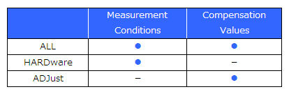
Turns the open / short compensation function on and off during DC measurement. |
Query |
Returns the open / short compensation function's on/off setting during DC measurement. |
|
Example |
Command |
:CORRection:LIMit:DC ON |
Query |
:CORRection:LIMit:DC? |
|
Response |
:CORRECTION:LIMIT:DC ON
(when HEADER ON) |
|
Note |
This setting applies to all compensation. |
Syntax |
Command |
:CORRection:LIMit:POINt <UNLimited/Compensation minimum frequency>, <UNLimited/Compensation maximum frequency> |
Query |
:CORRection:LIMit:POINt? |
|
Response |
<UNLIMITED/Compensation minimum frequency>, <UNLIMITED/Compensation maximum frequency> |
|
Parameter |
<Compensation minimum frequency> = 4.00 to 8.0000E+06 (NR3) |
|
Explanation |
Command |
Sets the open / short compensation range during AC measurement. |
Query |
Returns the open / short compensation range during AC measurement. |
|
Example |
Command |
:CORRection:LIMit:POINt 100E3, 200E3 |
Query |
:CORRection:LIMit:POINt? |
|
Response |
:CORRECTION:LIMIT:POINT 100.00E+03, UNLIMITED
(when HEADER ON) |
|
Note |
This setting applies to all compensation. |
Syntax |
Command |
:CORRection:OPEN <OFF/ALL/SPOT/CANCel> |
Query |
:CORRection:OPEN? |
|
Response |
<OFF/ALL/SPOT> |
|
Parameter |
|
|
Explanation |
Command |
Sets the open compensation function and acquires or cancels acquisition of the compensation value. OFF: Disables the open compensation function. |
Query |
Returns the setting of the open compensation function. OFF: The open compensation function is disabled. |
|
Example |
Command |
:CORRection:OPEN ALL |
Query |
:CORRection:OPEN? |
|
Response |
:CORRECTION:OPEN ALL
(when HEADER ON) |
|
Note |
Compensation cannot be executed during measurement as doing so will result in an execution error.
|
Syntax |
Command |
|
Query |
:CORRection:OPEN:ERRor? |
|
Response |
<Result> |
|
Parameter |
<Result> = 0/1/2/4/6 (NR1) |
|
Explanation |
Command |
|
Query |
Returns the result of executing open compensation. 0: Open compensation ended normally. |
|
Example |
Command |
|
Query |
:CORRection:OPEN:ERRor? |
|
Response |
:CORRECTION:OPEN:ERROR 6
(when HEADER ON) |
|
Note |
If [bit0=1] is returned for this command, the compensation is canceled because a compansation state of measurement cable is abnormal.Please retry compensation, refer to "section 5.4" in the instruction manual. |
Syntax |
Command |
:CORRection:OPEN:FREQuency <Compensation No.>,<OFF/ DC/ Frequency> |
Query |
:CORRection:OPEN:FREQuency? <Compensation No.> |
|
Response |
<OFF/ DC/ Frequency> |
|
Parameter |
<Compensation No.> = 1/ 2/ 3/ 4/ 5 |
|
Explanation |
Command |
Sets the frequency for performing SPOT compensation with the open compensation function. OFF: Disables SPOT compensation of the specified compensation number. |
Query |
Returns the SPOT compensation frequency of the open compensation function. OFF: The SPOT compensation frequency of the specified compensation number is not set. |
|
Example |
Command |
:CORRection:OPEN:FREQuency 1,120E+3 |
Query |
:CORRection:OPEN:FREQuency? 1 |
|
Response |
:CORRECTION:OPEN:FREQUENCY 120.00E+03
(when HEADER ON) |
|
Note |
|
Syntax |
Command |
:CORRection:OPEN:RETurn <OFF/ALL/SPOT> |
Query |
:CORRection:OPEN:RETurn? |
|
Response |
<OFF/ALL/SPOT> |
|
Parameter |
|
|
Explanation |
Command |
Sets the open compensation function. The compensation values are not acquired. OFF: Disables the open compensation function. |
Query |
Returns the open compensation setting. OFF: The open compensation function is disabled. |
|
Example |
Command |
:CORRection:OPEN:RETurn SPOT |
Query |
:CORRection:OPEN:RETurn? |
|
Response |
:CORRECTION:OPEN:RETURN SPOT
(when HEADER ON) |
|
Note |
|
Syntax |
Command |
|
Query |
:CORRection:OPEN:DATA:ALL? |
|
Response |
<Open compensation frequency>, <Open compensation value G>, <Open compensation value B> (comma-delimited) for each compensation frequency |
|
Parameter |
<Open compensation frequency> = 0/4.00 to 8.0000E+06 (NR3) |
|
Explanation |
Command |
|
Query |
Returns the open compensation values acquired for all compensation frequencies. |
|
Example |
Command |
|
Query |
:CORRection:OPEN:DATA:ALL? |
|
Response |
0.0000E+00, -0.0786E-09, 0.0000E-09, 20.000E+00, 0.0062E-09, 0.0118E-09, .... ... ... , 200.00E+03, 9.102775E-06, 7.158449E-06
|
|
Note |
The open compensation value output format is the same as the MEASure response format (G, B). |
Syntax |
Command |
|
Query |
:CORRection:OPEN:DATA:SPOT? <Compensation No.> |
|
Response |
<Open compensation frequency>, <Open compensation value G>, <Open compensation value B> |
|
Parameter |
<Compensation no.> = 1/2/3/4/5 |
|
Explanation |
Command |
|
Query |
Returns the open compensation value specified with the compensation number. |
|
Example |
Command |
|
Query |
:CORRection:OPEN:DATA:SPOT? 2 |
|
Response |
120.00E+03, 23.7354E-09, 341.7050E-09
|
|
Note |
The open compensation value output format is the same as the MEASure response format (G, B). |
Syntax |
Command |
:CORRection:SHORt <OFF/ALL/SPOT/CANCel> |
Query |
:CORRection:SHORt? |
|
Response |
<OFF/ALL/SPOT> |
|
Parameter |
|
|
Explanation |
Command |
Sets the short compensation function and acquires or cancels the acquisition of the compensation value. OFF: Disables the short compensation function. |
Query |
Returns the setting of the short compensation function. OFF: The short compensation function is disabled. |
|
Example |
Command |
:CORRection:SHORt ALL |
Query |
:CORRection:SHORt? |
|
Response |
:CORRECTION:SHORT ALL
(when HEADER ON) |
|
Note |
This command cannot be executed during measurement, and doing so will result in an execution error. Execute the command after changing to an external trigger (in LCR mode).
|
Syntax |
Command |
|
Query |
:CORRection:SHORt:ERRor? |
|
Response |
<Result> |
|
Parameter |
<Result> = 0/ 1/ 2 (NR1) |
|
Explanation |
Command |
|
Query |
Returns the result of executing short compensation. 0: Short compensation ended normally. |
|
Example |
Command |
|
Query |
:CORRection:SHORt:ERRor? |
|
Response |
:CORRECTION:SHORT:ERROR 0
(when HEADER ON) |
|
Note |
If [2] is returned for this command, the compensation value is being acquired in the state in which auto ranging has not determined the range. |
Syntax |
Command |
:CORRection:SHORt:FREQuency <Compensation No.>,<OFF/ DC/ Frequency> |
Query |
:CORRection:SHORt:FREQuency? <Compensation No.> |
|
Response |
<OFF/ DC/ Frequency> |
|
Parameter |
<Compensation No.> = 1/ 2/ 3/ 4/ 5 |
|
Explanation |
Command |
Sets the frequency for performing SPOT compensation with the short compensation function. OFF: Disables SPOT compensation of the specified compensation number. |
Query |
Returns the SPOT compensation frequency of the short compensation function. OFF: The SPOT compensation frequency of the specified compensation number is not set. |
|
Example |
Command |
:CORRection:SHORt:FREQuency 1,120E+3 |
Query |
:CORRection:SHORt:FREQuency? 1 |
|
Response |
:CORRECTION:SHORT:FREQUENCY 120.00E+03
(when HEADER ON) |
|
Note |
|
Syntax |
Command |
:CORRection:SHORt:RETurn <OFF/ALL/SPOT> |
Query |
:CORRection:SHORt:RETurn? |
|
Response |
<OFF/ALL/SPOT> |
|
Parameter |
|
|
Explanation |
Command |
Sets the short compensation function. The compensation values are not acquired. OFF: Disables the short compensation function. |
Query |
Returns the setting of the short compensation function. OFF: The short compensation function is disabled. |
|
Example |
Command |
:CORRection:SHORt:RETurn SPOT |
Query |
:CORRection:SHORt:RETurn? |
|
Response |
:CORRECTION:SHORT:RETURN SPOT
(when HEADER ON) |
|
Note |
The SPOT compensation cannot be set unless the frequency is set. |
Syntax |
Command |
|
Query |
:CORRection:SHORt:DATA:ALL? |
|
Response |
<Short compensation frequency>, <Open compensation value R>, <Open compensation value X> (comma delimited) for each compensation frequency |
|
Parameter |
<Short compensation frequency> = 0/4.00 to 8.0000E+06 (NR3) |
|
Explanation |
Command |
|
Query |
Returns the short compensation values acquired for all compensation frequencies. |
|
Example |
Command |
|
Query |
:CORRection:SHORt:DATA:ALL? |
|
Response |
0.0000E+00, 11.742E-03, 0.0000E+00, 20.000E+00, 11.741E-03, -0.002E-03, ... ... ... , 200.00E+03, 89.957E-03, 450.797E-03
|
|
Note |
The short compensation value output format is the same as the MEASure response format (R, X). |
Syntax |
Command |
|
Query |
:CORRection:SHORt:DATA:SPOT? <Compensation No.> |
|
Response |
<Short compensation frequency>, <Open compensation value R>, <Open compensation value X> |
|
Parameter |
<Compensation no.> = 1/2/3/4/5 |
|
Explanation |
Command |
|
Query |
Returns the short compensation value specified with the compensation number. |
|
Example |
Command |
|
Query |
:CORRection:SHORt:DATA:SPOT? 2 |
|
Response |
120.00E+03, 2.720E-03, 26.536E-03
|
|
Note |
The short compensation value output format is the same as the MEASure response format (R, X). |
Syntax |
Command |
:CORRection:LOAD <OFF/ON> |
Query |
:CORRection:LOAD? |
|
Response |
<OFF/ON> |
|
Parameter |
|
|
Explanation |
Command |
Sets the load compensation function and acquires the compensation value. OFF: Disables the load compensation function. |
Query |
Returns the setting of the load compensation function. |
|
Example |
Command |
:CORRection:LOAD ON |
Query |
:CORRection:LOAD? |
|
Response |
:CORRECTION:LOAD ON
(when HEADER ON) |
|
Note |
Set the load compensation conditions before acquiring the load compensation value.
|
Syntax |
Command |
:CORRection:LOAD:CONDition <Compensation No.>,<Frequency>,<Range No.>,<LOW Z>,<V/ CV /CC>,<Level value>,<DC bias>,<DC bias value> |
Query |
:CORRection:LOAD:CONDition? <Compensation No.> |
|
Response |
<Frequency>,<Range No.>,<LOW Z>,<V/ CV /CC>,<Level value>,<DC bias>,<DC bias value> |
|
Parameter |
<Compensation No.> = 1/ 2/ 3/ 4/ 5 |
|
Explanation |
Command |
Sets the load compensation conditions. |
Query |
Returns the load compensation conditions. |
|
Example |
Command |
:CORRection:LOAD:CONDition 3,5.0000E+03,3,ON,CV,0.300,ON,0.1 Frequency: 5.0000 kHz |
Query |
:CORRection:LOAD:CONDition? 3 |
|
Response |
:CORRECTION:LOAD:CONDITION 5.0000E+03,3,ON,CV,0.300,ON,0.1
(when HEADER ON) Frequency: 5.0000 kHz |
|
Note |
If this command is executed when the setting last time was the DC setting, the parameter to be used for the reference value is changed to Z-θ, and the reference value is cleared.
|
Syntax |
Command |
:CORRection:LOAD:DCResistance:CONDition <Compensation No.>,<Range No.>,<LOW Z> |
Query |
:CORRection:LOAD:DCResistance:CONDition? <Compensation No.> |
|
Response |
<Range No.>,<LOW Z> |
|
Parameter |
<Compensation No.> = 1/ 2/ 3/ 4/ 5 |
|
Explanation |
Command |
Sets the load compensation conditions for when DC resistance measurement. |
Query |
Returns the load compensation conditions for when DC resistance measurement. |
|
Example |
Command |
:CORRection:LOAD:DCResistance:CONDition 5,6,OFF Range: 6 (10 kΩ range) |
Query |
:CORRection:LOAD:DCResistance:CONDition? 5 |
|
Response |
:CORRECTION:LOAD:DCRESISTANCE:CONDITION 6,OFF
(when HEADER ON) Range: 6 (10 kΩ range) |
|
Note |
If this command is executed and the setting last time was not the DC setting, the parameter to use for the reference value is changed to Rdc, and the reference value is cleared.
|
Syntax |
Command |
:CORRection:LOAD:DCResistance:REFerence <Compensation No.>,<Reference value> |
Query |
:CORRection:LOAD:DCResistance:REFerence? <Compensation No.> |
|
Response |
<Reference value> |
|
Parameter |
<Compensation No.> = 1/ 2/ 3/ 4/ 5 |
|
Explanation |
Command |
Sets the reference value to use for load compensation for when DC resistance measurement. |
Query |
Returns the reference value to use for load compensation for when DC resistance measurement. |
|
Example |
Command |
:CORRection:LOAD:DCResistance:REFerence 1,20 |
Query |
:CORRection:LOAD:DCResistance:REFerence? 1 |
|
Response |
:CORRECTION:LOAD:DCRESISTANCE:REFERENCE 20.00000E+00
(when HEADER ON) |
|
Note |
An execution error occurs in the following cases.
|
Syntax |
Command |
|
Query |
:CORRection:LOAD:DATA? <Compensation No.> |
|
Response |
<Compensation coefficient 1>, <Compensation coefficient 2> |
|
Parameter |
<Compensation No.> = 1/ 2/ 3/ 4/ 5 |
|
Explanation |
Command |
|
Query |
Returns the compensation coefficient acquired by executing load compensation. |
|
Example |
Command |
|
Query |
:CORRection:LOAD:DATA? 1 |
|
Response |
225.661E-03, -61.18
|
|
Note |
If the compensation mode is DC, only compensation coefficient 1 is returned. |
Syntax |
Command |
|
Query |
:CORRection:LOAD:ERRor? |
|
Response |
<Result> |
|
Parameter |
<Result> = 0/ 1 (NR1) |
|
Explanation |
Command |
|
Query |
Returns the result of executing load compensation. 0: Load compensation ended normally. |
|
Example |
Command |
|
Query |
:CORRection:LOAD:ERRor? |
|
Response |
:CORRECTION:LOAD:ERROR 0
(when HEADER ON) |
|
Note |
|
Syntax |
Command |
:CORRection:LOAD:REFerence <Compensation No.>,<Mode No.>,<Reference value1>,<Reference value2> |
Query |
:CORRection:LOAD:REFerence? <Compensation No.> |
|
Response |
<Mode No.>,<Reference value1>,<Reference value2> |
|
Parameter |
<Compensation No.> = 1/ 2/ 3/ 4/ 5 |
|
Explanation |
Command |
Sets the parameter and reference values to use for the reference values for load compensation. |
Query |
Returns the parameter and reference values to use for the reference value for load compensation. |
|
Example |
Command |
:CORRection:LOAD:REFerence 1,2,10e-9,0.00014 |
Query |
:CORRection:LOAD:REFerence? 1 |
|
Response |
:CORRECTION:LOAD:REFERENCE 2,10.0000E-09,140.000E-06
(when HEADER ON) |
|
Note |
An execution error occurs in the following cases.
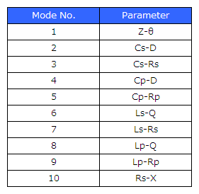
|
Syntax |
Command |
:CORRection:LOAD:RESet <Compensation No.> |
Query |
|
|
Response |
|
|
Parameter |
<Compensation No.> = 1/ 2/ 3/ 4/ 5 |
|
Explanation |
Command |
Clears the load compensation conditions of the specified compensation number. |
Query |
|
|
Example |
Command |
:CORRection:LOAD:RESet 1 |
Query |
|
|
Response |
|
|
Note |
The load compensation conditions cannot be restored once they are cleared. |
Syntax |
Command |
:CORRection:LOAD:RETurn <OFF/ON> |
Query |
:CORRection:LOAD:RETurn? |
|
Response |
<OFF/ON> |
|
Parameter |
|
|
Explanation |
Command |
Sets the load compensation function. The compensation values are not acquired. OFF: Disables the load compensation function. |
Query |
Returns the setting of the load compensation function. |
|
Example |
Command |
:CORRection:LOAD:RETurn ON |
Query |
:CORRection:LOAD:RETurn? |
|
Response |
:CORRECTION:LOAD:RETURN ON
(when HEADER ON) |
|
Note |
|
Syntax |
Command |
:CORRection:CABLe <Cable length> |
Query |
:CORRection:CABLe? |
|
Response |
<Cable length> |
|
Parameter |
<Cable length> = 0/1/2/4 (NR1) |
|
Explanation |
Command |
Sets the cable length compensation function. |
Query |
Returns the setting of the cable length compensation function. 0: The cable length compensation function is set to 0 m. |
|
Example |
Command |
:CORRection:CABLe 1 |
Query |
:CORRection:CABLe? |
|
Response |
:CORRECTION:CABLE 1
(when HEADER ON) |
|
Note |
|
Syntax |
Command |
:CORRection:SCALe <OFF/ON> |
Query |
:CORRection:SCALe? |
|
Response |
<OFF/ON> |
|
Parameter |
|
|
Explanation |
Command |
Sets the scaling compensation function. |
Query |
Returns the setting of the scaling compensation function. |
|
Example |
Command |
:CORRection:SCALe ON |
Query |
:CORRection:SCALe? |
|
Response |
:CORRECTION:SCALE ON
(when HEADER ON) |
|
Note |
|
Syntax |
Command |
:CORRection:SCALe:DATA <Scaling No.>,<Compensation value A>,<Compensation value B> |
Query |
:CORRection:SCALe:DATA? <Scaling No.> |
|
Response |
<Compensation value A>,<Compensation value B> |
|
Parameter |
<Scaling No.> = 1/ 2/ 3/ 4 |
|
Explanation |
Command |
Sets the values of the scaling compensation function. |
Query |
Returns the values of the scaling compensation function. |
|
Example |
Command |
:CORRection:SCALe:DATA 1,1.23,4.56 |
Query |
:CORRection:SCALe:DATA? 1 |
|
Response |
:CORRECTION:SCALE:DATA 1.230,4.56000E+00
(when HEADER ON) |
|
Note |
Values within the range from -0.001 to 0.001 cannot be set as compensation value A. |
Syntax |
Command |
:CONTinuous:DRAW <REAL/AFTer> |
Query |
:CONTinuous:DRAW? |
|
Response |
<REAL/AFTER> |
|
Parameter |
|
|
Explanation |
Command |
Sets the display update timing of continuous measurement mode. REAL: Updates display in real time after one measurement finishes. |
Query |
Returns the setting of the display update timing of continuous measurement mode. |
|
Example |
Command |
:CONTinuous:DRAW REAL |
Query |
:CONTinuous:DRAW? |
|
Response |
:CONTINUOUS:DRAW REAL
(when HEADER ON) |
|
Note |
|
Syntax |
Command |
:CONTinuous:EXECution <Panel No.>, <ON/OFF> |
Query |
:CONTinuous:EXECution? <Panel No.> |
|
Response |
<ON/OFF> |
|
Parameter |
<Panel No.> = 1 to 128 / ALL |
|
Explanation |
Command |
Sets the panel to be the measurement target in continuous measurement mode. |
Query |
Returns the setting of the panel to be the measurement target in continuous measurement mode. |
|
Example |
Command |
:CONTinuous:EXECution 5,ON |
Query |
:CONTinuous:EXECution? 5 |
|
Response |
:CONTINUOUS:EXECUTION ON
(when HEADER ON) |
|
Note |
ALL can only be specified for the parameter in the command. It cannot be used in the query. |
Syntax |
Command |
|
Query |
:CONTinuous:COUNt? |
|
Response |
<Panel count> |
|
Parameter |
<Panel count> = 0 to 60 (NR1) |
|
Explanation |
Command |
|
Query |
Returns the panel count targeted for measurement in continuous measurement mode. |
|
Example |
Command |
|
Query |
:CONTinuous:COUNt? |
|
Response |
:CONTINUOUS:COUNT 5
(when HEADER ON) |
|
Note |
|
Syntax |
Command |
|
Query |
:MEASure? <No data/ ALL> |
|
Response |
|
|
Parameter |
|
|
Explanation |
Command |
|
Query |
For more detail, refer to "Querying measurement data". |
|
Example |
Command |
|
Query |
|
|
Response |
|
|
Note |
If a setting has been changed, send the ":MEASure?" query after triggering. |
Syntax |
Command |
|
Query |
:MEASure:CONTinuous:COMParator? |
|
Response |
<Judgment result> |
|
Parameter |
<Judgment result> = 0,1 (NR1) |
|
Explanation |
Command |
|
Query |
Returns the setting of the overall judgment result at the time of continuous measurement. |
|
Example |
Command |
|
Query |
:MEASure:CONTinuous:COMParator? |
|
Response |
:MEASURE:CONTINUOUS:COMPARATOR 1
(when HEADER ON) |
|
Note |
|
Syntax |
Command |
:WAVE <ON/OFF> |
Query |
:WAVE? |
|
Response |
<ON/OFF> |
|
Parameter |
|
|
Explanation |
Command |
Sets the waveform averaging function. |
Query |
Returns the setting of the waveform averaging function. |
|
Example |
Command |
:WAVE ON |
Query |
:WAVE? |
|
Response |
:WAVE ON
(when HEADER ON) |
|
Note |
|
Syntax |
Command |
:WAVE:NUM <Frequency No.>,<number of measurement waveforms> |
Query |
:WAVE:NUM? <Frequency No.> |
|
Response |
<number of measurement waveforms> |
|
Parameter |
<Frequency No.> = 1 to 29 (NR1) |
|
Explanation |
Command |
Sets the number of measurement waveforms for the waveform averaging function. |
Query |
Returns the number of measurement waveforms for the waveform averaging function. |
|
Example |
Command |
:WAVE:NUM 5,40 |
Query |
:WAVE:NUM? 5 |
|
Response |
:WAVE:NUM 40
(when HEADER ON) |
|
Note |
The settable range for the number of measurement waveforms varies depending on the frequency zone. |
Syntax |
Command |
:WAVE:RESet <FAST/MEDium/SLOW/SLOW2> |
Query |
|
|
Response |
|
|
Parameter |
|
|
Explanation |
Command |
Resets the number of measurement waveforms for the waveform averaging function to that of each measurement speed. |
Query |
|
|
Example |
Command |
:WAVE:RESet FAST |
Query |
|
|
Response |
|
|
Note |
|
Syntax |
Command |
:CCHeck:VERify <OFF/BEFore/AFTer/BOTH> |
Query |
:CCHeck:VERify? |
|
Response |
<OFF/BEFore/AFTer/BOTH> |
|
Parameter |
|
|
Explanation |
Command |
Sets the contact check function. |
Query |
Returns the setting of the contact check function. |
|
Example |
Command |
:CCHeck:VERify AFTer |
Query |
:CCHeck:VERify? |
|
Response |
:CCHECK:VERIFY AFTER
(when HEADER ON) |
|
Note |
When the contact check function is set to "BEFore" or "BOTH", the trigger synchronous output function is automatically set to "ON". |
Syntax |
Command |
:CCHeck:SENSitivity <Settable range> |
Query |
:CCHeck:SENSitivity? |
|
Response |
<Settable range> |
|
Parameter |
<Settable range> = 1 to 5 (NR1) |
|
Explanation |
Command |
Sets the settable range of the contact check function. |
Query |
Returns the settable range for the contact check function. |
|
Example |
Command |
:CCHeck:SENSitivity 5 |
Query |
:CCHeck:SENSitivity? |
|
Response |
:CCHECK:SENSITIVITY 5
(when HEADER ON) |
|
Note |
|
Syntax |
Command |
:CCHeck:DELay <Delay time> |
Query |
:CCHeck:DELay? |
|
Response |
<Delay time> |
|
Parameter |
<Delay time> = 0.0000 to 1.0000 (NR2) |
|
Explanation |
Command |
Sets the contact check delay time. |
Query |
Returns the contact check delay time. |
|
Example |
Command |
:CCHeck:DELay 0.0001 |
Query |
:CCHeck:DELay? |
|
Response |
:CCHECK:DELAY 0.0001
(when HEADER ON) |
|
Note |
|
Syntax |
Command |
:HIZ <ON/OFF> |
Query |
:HIZ? |
|
Response |
<ON/OFF> |
|
Parameter |
|
|
Explanation |
Command |
Enables or disables the Hi Z reject function. OFF: Does not detect abnormal measurement values. |
Query |
Returns whether the Hi Z reject function is enabled or disabled. |
|
Example |
Command |
:HIZ ON |
Query |
:HIZ? |
|
Response |
:HIZ ON
(when HEADER ON) |
|
Note |
|
Syntax |
Command |
:HIZ:LIMit <Limit value> |
Query |
:HIZ:LIMit? |
|
Response |
<Limit value> |
|
Parameter |
<Limit value> = 0 to 30000% (NR1) |
|
Explanation |
Command |
Sets the limit value of the Hi Z reject function. |
Query |
Returns the limit value of the Hi Z reject function. |
|
Example |
Command |
:HIZ:LIMit 500 |
Query |
:HIZ:LIMit? |
|
Response |
:HIZ:LIMIT 500
(when HEADER ON) |
|
Note |
|
Syntax |
Command |
|
Query |
:MEMory? <No data/ ALL> |
|
Response |
Refer to the response format of the MEASure? command. |
|
Parameter |
|
|
Explanation |
Command |
|
Query |
In the case of :MEMory? ALLSlash (/)
|
|
Example |
Command |
|
Query |
:MEMory? |
|
Response |
Z 1.59062E+03,PHASE -89.992 |
|
Note |
An execution error occurs during continuous measurement. |
Syntax |
Command |
:MEMory:CLEar |
Query |
|
|
Response |
|
|
Parameter |
|
|
Explanation |
Command |
Clears all of the measurement values saved to internal memory with the measurement value memory function. |
Query |
|
|
Example |
Command |
:MEMory:CLEar |
Query |
|
|
Response |
|
|
Note |
|
Syntax |
Command |
:MEMory:CONTrol <ON/IN/OFF> |
Query |
:MEMory:CONTrol? |
|
Response |
<ON/IN/OFF> |
|
Parameter |
|
|
Explanation |
Command |
Sets the measurement value memory function. OFF : Measurement values are not saved to internal memory. |
Query |
Returns the setting of the measurement value memory function. |
|
Example |
Command |
:MEMory:CONTrol ON |
Query |
:MEMory:CONTrol? |
|
Response |
:MEMORY:CONTROL ON
(when HEADER ON) |
|
Note |
An execution error occurs during continuous measurement. |
Syntax |
Command |
|
Query |
:MEMory:COUNt? |
|
Response |
<Number of data items> |
|
Parameter |
<Number of data items> = 0 to 32000 (NR1) |
|
Explanation |
Command |
|
Query |
Returns the number of data items saved to memory with the measurement value memory function. |
|
Example |
Command |
|
Query |
:MEMory:COUNt? |
|
Response |
1000
|
|
Note |
|
Syntax |
Command |
:MEMory:POINts <Memory size> |
Query |
:MEMory:POINts? |
|
Response |
<Memory size> |
|
Parameter |
<Memory size> = 1 to 32000 (NR1) |
|
Explanation |
Command |
Sets the number of data items to save to internal memory. |
Query |
Returns the number of data items to save to internal memory. |
|
Example |
Command |
:MEMory:POINts 200 |
Query |
:MEMory:POINts? |
|
Response |
:MEMORY:POINTS 200
(when HEADER ON) |
|
Note |
An execution error occurs during continuous measurement. |
Syntax |
Command |
:MEMory:SAVE |
Query |
|
|
Response |
|
|
Parameter |
|
|
Explanation |
Command |
Copies data saved to internal memory with the measured value memory function to USB memory. |
Query |
|
|
Example |
Command |
:MEMory:SAVE |
Query |
|
|
Response |
|
|
Note |
If data has not been saved in internal memory, an execution error will result. |
Syntax |
Command |
:DISPlay <ON/OFF> |
Query |
:DISPlay? |
|
Response |
<ON/OFF> |
|
Parameter |
|
|
Explanation |
Command |
Sets LCD display. ON: Sets the LCD to always on. |
Query |
Returns the setting of LCD display. |
|
Example |
Command |
:DISPlay OFF |
Query |
:DISPlay? |
|
Response |
:DISPLAY OFF
(when HEADER ON) |
|
Note |
|
Syntax |
Command |
:ZOOM <ON/OFF> |
Query |
:ZOOM? |
|
Response |
<ON/OFF> |
|
Parameter |
|
|
Explanation |
Command |
Sets the zoom function. |
Query |
Returns the setting of the zoom function. |
|
Example |
Command |
:ZOOM ON |
Query |
:ZOOM? |
|
Response |
:ZOOM ON
(when HEADER ON) |
|
Note |
|
Syntax |
Command |
:IO:BCD <OFF/ON> |
Query |
:IO:BCD? |
|
Response |
<OFF/ON> |
|
Parameter |
|
|
Explanation |
Command |
Sets the BCD output function. OFF: Disables the BCD output function. |
Query |
Returns ON or OFF for the BCD output function. |
|
Example |
Command |
IO:BCD ON |
Query |
IO:BCD? |
|
Response |
IO:BCD ON
(when HEADER ON) |
|
Note |
|
Syntax |
Command |
:IO:BCD:DECimal <Parameter No.>, <Decimal point> |
Query |
:IO:BCD:DECimal? <Parameter No.> |
|
Response |
<Decimal point> |
|
Parameter |
<Parameter No.> = 0,1 (NR1) |
|
Explanation |
Command |
Sets decimal point of the BCD output function. |
Query |
Returns decimal point of the BCD output function. |
|
Example |
Command |
:IO:BCD:DECimal 0,0 |
Query |
:IO:BCD:DECimal? 1 |
|
Response |
:IO:BCD:DECIMAL 20
(when HEADER ON) |
|
Note |
|
Syntax |
Command |
:KEYLock |
Query |
:KEYLock? |
|
Response |
<ON/OFF> |
|
Parameter |
|
|
Explanation |
Command |
Enables the key lock. |
Query |
Returns the state of the key lock. OFF: The key lock is not enabled. |
|
Example |
Command |
:KEYLock |
Query |
:KEYLock? |
|
Response |
:KEYLOCK ON
(when HEADER ON) |
|
Note |
An execution error occurs if this command is sent while the key lock is enabled. |
Syntax |
Command |
:KEYLock:PASScode <Passcode/ none> |
Query |
|
|
Response |
|
|
Parameter |
<Passcode> = 0 to 9 (up to 4 digits) |
|
Explanation |
Command |
Sets the passcode of the key lock. |
Query |
|
|
Example |
Command |
:KEYLock:PASScode 0523 |
Query |
|
|
Response |
|
|
Note |
An execution error occurs in the following cases.
|
Syntax |
Command |
:KEYLock:UNLock <Passcode/ none> |
Query |
|
|
Response |
|
|
Parameter |
<Passcode> = 0 to 9 (up to 4 digits) |
|
Explanation |
Command |
Disables the key lock. |
Query |
|
|
Example |
Command |
:KEYLock:UNLock 0523 |
Query |
|
|
Response |
|
|
Note |
An execution error occurs in the following cases.
|
Syntax |
Command |
:BEEPer:JUDGment <OFF/IN/NG> |
Query |
:BEEPer:JUDGment? |
|
Response |
<OFF/IN/NG> |
|
Parameter |
|
|
Explanation |
Command |
Sets the beep sound for the judgment results of measurement values. OFF: No beep sound. |
Query |
Returns the setting of the beep sound for the judgment results of measurement values. |
|
Example |
Command |
:BEEPer:JUDGment NG |
Query |
:BEEPer:JUDGment? |
|
Response |
:BEEPER:JUDGMENT NG
(when HEADER ON) |
|
Note |
|
Syntax |
Command |
:BEEPer:KEY <ON/OFF> |
Query |
:BEEPer:KEY? |
|
Response |
<ON/OFF> |
|
Parameter |
|
|
Explanation |
Command |
Sets the beep sound for key operation. ON: A beep sound is emitted. |
Query |
Returns the setting of the beep sound for key operation. |
|
Example |
Command |
:BEEPer:KEY ON |
Query |
:BEEPer:KEY? |
|
Response |
:BEEPER:KEY ON
(when HEADER ON) |
|
Note |
|
Syntax |
Command |
:BEEPer:TONE <A/B/C/D> |
Query |
:BEEPer:TONE? |
|
Response |
<A/B/C/D> |
|
Parameter |
|
|
Explanation |
Command |
Sets the beep tone type. |
Query |
Returns the beep tone type. |
|
Example |
Command |
:BEEPer:TONE C |
Query |
:BEEPer:TONE? |
|
Response |
:BEEPER:TONE C
(when HEADER ON) |
|
Note |
|
Syntax |
Command |
:CALCulate:PARameter <CS/ CP> |
Query |
:CALCulate:PARameter? |
|
Response |
<CS/ CP> |
|
Parameter |
|
|
Explanation |
Command |
Sets the parameters during calculation of conductivity/permittivity. |
Query |
Returns the parameter setting during calculation of conductivity/permittivity. |
|
Example |
Command |
:CALCulate:PARameter CS |
Query |
:CALCulate:PARameter? |
|
Response |
:CALCULATE:PARAMETER CS
(when HEADER ON) |
|
Note |
|
Syntax |
Command |
:CALCulate:LENGth <Length of conductor> |
Query |
:CALCulate:LENGth? |
|
Response |
<Length of conductor> |
|
Parameter |
<Length of conductor> = 0.000001 to 1000000 (NR2) |
|
Explanation |
Command |
Sets the length of the conductor during calculation of conductivity/permittivity. |
Query |
Returns the setting of the length of the conductor during calculation of conductivity/permittivity. |
|
Example |
Command |
:CALCulate:LENGth 30 |
Query |
:CALCulate:LENGth? |
|
Response |
:CALCULATE:LENGTH 30.00000
(when HEADER ON) |
|
Note |
|
Syntax |
Command |
:CALCulate:AREA <Cross-sectional area of conductor> |
Query |
:CALCulate:AREA? |
|
Response |
<Cross-sectional area of conductor> |
|
Parameter |
<Cross-sectional area of conductor> = 0.000001 to 1000000 (NR2) |
|
Explanation |
Command |
Sets the cross-sectional area of the conductor during calculation of the conductivity/permittivity. |
Query |
Returns the setting of the cross-sectional area of the conductor during calculation of conductivity/permittivity. |
|
Example |
Command |
:CALCulate:AREA 10 |
Query |
:CALCulate:AREA? |
|
Response |
:CALCULATE:AREA 10.00000
(when HEADER ON) |
|
Note |
|
Syntax |
Command |
:SIGMa <Length of conductor>, <Cross-sectional area of conductor> |
Query |
:SIGMa? |
|
Response |
<Length of conductor>, <Cross-sectional area of conductor> |
|
Parameter |
<Length of conductor> = 0.000001 to 1000000 (NR2) |
|
Explanation |
Command |
Sets the length and cross-sectional area of the conductor during calculation of conductivity. |
Query |
Returns the setting of the length and cross-sectional area of the conductor during calculation of conductivity. |
|
Example |
Command |
:SIGMa 30,10 |
Query |
:SIGMa? |
|
Response |
:SIGMA 30,10
(when HEADER ON) |
|
Note |
|
Syntax |
Command |
:IO:EOM:MODE <HOLD/PULSe> |
Query |
:IO:EOM:MODE? |
|
Response |
|
|
Parameter |
|
|
Explanation |
Command |
Sets the INDEX and EOM output method. |
Query |
Returns the INDEX and EOM output method. |
|
Example |
Command |
IO:EOM:MODE PULSE |
Query |
IO:EOM:MODE? |
|
Response |
:IO:EOM:MODE PULSE
(when HEADER ON) |
|
Note |
For a timing chart describing the setting made with this command, see the "External Control" chapter in the instrument's user manual. |
Syntax |
Command |
:IO:EOM:PULSe <Pulse width> |
Query |
:IO:EOM:PULSe? |
|
Response |
|
|
Parameter |
<Pulse width> = 0.0001 to 0.9999s (NR2) |
|
Explanation |
Command |
Sets the pulse width for which to keep EOM low (on). |
Query |
Returns the pulse width for which to keep EOM low (on). |
|
Example |
Command |
IO:EOM:PULSe 0.002 |
Query |
IO:EOM:PULSe? |
|
Response |
:IO:EOM:PULSE 0.0020
(when HEADER ON) |
|
Note |
For a timing chart describing the setting made with this command, see the "External Control" chapter in the instrument's user manual. |
Syntax |
Command |
:IO:OUTPut:DELay <I/O delay time> |
Query |
:IO:OUTPut:DELay? |
|
Response |
<I/O delay time> |
|
Parameter |
<I/O delay time> = 0 to 0.9999 s (NR2) |
|
Explanation |
Command |
Sets the delay time for the period between the output of comparator and BIN judgment results and the output of the EOM from the EXT I/O. |
Query |
Returns the delay time for the period between the output of comparator and BIN judgment results and the output of the EOM from the EXT I/O. |
|
Example |
Command |
:IO:OUTPUT:DELAY 0.1234 |
Query |
:IO:OUTPUT:DELAY? |
|
Response |
:IO:OUTPUT:DELAY 0.1234
(when HEADER ON) |
|
Note |
The delay time for the period between the comparator and BIN judgment results and the |
Syntax |
Command |
:IO:RESult:RESet <ON/OFF> |
Query |
:IO:RESult:RESet? |
|
Response |
<ON/OFF> |
|
Parameter |
|
|
Explanation |
Command |
Sets whether the judgment result signal line of the EXT I/O is reset. ON: Resets the judgment results simultaneously with the input of a measurement start signal (trigger signal). |
Query |
Returns whether the judgment result signal line of the EXT I/O is reset. |
|
Example |
Command |
:IO:RESult:RESet ON |
Query |
:IO:RESult:RESet? |
|
Response |
:IO:RESULT:RESET ON
(when HEADER ON) |
|
Note |
For details on the judgment result signal line, refer to "External Control" in the instruction manual. |
Syntax |
Command |
:IO:TRIGger:EDGe <DOWN/UP> |
Query |
:IO:TRIGger:EDGe? |
|
Response |
<DOWN/UP> |
|
Parameter |
|
|
Explanation |
Command |
Sets the trigger edge of the EXT I/O. DOWN: Applies a trigger to the falling edge. |
Query |
Returns the setting of the trigger edge of the EXT I/O. |
|
Example |
Command |
:IO:TRIGger:EDGe UP |
Query |
:IO:TRIGger:EDGe? |
|
Response |
:IO:TRIGGER:EDGE UP
(when HEADER ON) |
|
Note |
|
Syntax |
Command |
:IO:TRIGger:ENABle <ON/OFF> |
Query |
:IO:TRIGger:ENABle? |
|
Response |
<ON/OFF> |
|
Parameter |
|
|
Explanation |
Command |
Enables or disables trigger input from the EXT I/O during measurement. ON: Accepts trigger input from the EXT I/O during measurement. |
Query |
Returns whether trigger input from the EXT I/O during measurement is enabled or disabled. |
|
Example |
Command |
:IO:TRIGger:ENABle ON |
Query |
:IO:TRIGger:ENABle? |
|
Response |
:IO:TRIGGER:ENABLE ON
(when HEADER ON) |
|
Note |
|
Syntax |
Command |
:SAVE <Panel No.>,<Panel name> |
Query |
:SAVE? <Panel name> |
|
Response |
<0/1> |
|
Parameter |
<Panel No.> = 1 to 128 (NR1) |
|
Explanation |
Command |
Specifies the panel number and saves the panel under the specified panel name. |
Query |
Returns 1 if a panel is saved to the specified panel number, and 0 if a panel is not saved. |
|
Example |
Command |
:SAVE 3,IM3536_003 |
Query |
:SAVE? 3 |
|
Response |
1
|
|
Note |
An error occurs in the following cases.
|
Syntax |
Command |
:SAVE:CLEar <ALL/ Panel No.> |
Query |
|
|
Response |
|
|
Parameter |
<Panel No.> = 1 to 128 (NR1) |
|
Explanation |
Command |
Clears the data of the specified panel number. ALL : Clears all of the panels. A command error occurs if there is no saved data for the specified panel number. |
Query |
|
|
Example |
Command |
:SAVE:CLEar 5 |
Query |
|
|
Response |
|
|
Note |
Data cannot be restored once it is cleared. |
Syntax |
Command |
|
Query |
:SAVE:NAME? <Panel No.> |
|
Response |
|
|
Parameter |
<Panel No.> = 1 to 128 (NR1) |
|
Explanation |
Command |
|
Query |
Returns the panel name of the specified panel number. |
|
Example |
Command |
|
Query |
:SAVE:NAME? 1 |
|
Response |
IM3536_001
|
|
Note |
|
Syntax |
Command |
:SAVE:REName <Panel No.>,<Panel name> |
Query |
|
|
Response |
|
|
Parameter |
<Panel No.> = 1 to 128 (NR1) |
|
Explanation |
Command |
Changes the panel name of the specified panel number. |
Query |
|
|
Example |
Command |
:SAVE:REName 1,IM3536_001 |
Query |
|
|
Response |
|
|
Note |
|
Syntax |
Command |
:SAVE:TYPE <ALL/HARDware/ADJust> |
Query |
:SAVE:TYPE? |
|
Response |
<ALL/HARDWARE/ADJUST> |
|
Parameter |
|
|
Explanation |
Command |
Sets the save type. |
Query |
Returns the setting of the save type. |
|
Example |
Command |
:SAVE:TYPE HARDware |
Query |
:SAVE:TYPE? |
|
Response |
:SAVE:TYPE HARDWARE
(when HEADER ON) |
|
Note |
|
Syntax |
Command |
|
Query |
:SAVE:MODE? <Panel No.> |
|
Response |
<Hard data type(LCR/OFF)>,<Compensation data type(ON/OFF)> |
|
Parameter |
<Panel No.> = 1 to 128 (NR1) |
|
Explanation |
Command |
|
Query |
Returns the setting of the save type. |
|
Example |
Command |
|
Query |
:SAVE:MODE? 1 |
|
Response |
:SAVE:MODE LCR,ON
(when HEADER ON) |
|
Note |
An execution error occurs if there is no data for the specified panel number. |
Syntax |
Command |
:LOAD <Panel No.> |
Query |
|
|
Response |
|
|
Parameter |
<Panel No.> = 1 to 128 |
|
Explanation |
Command |
Loads the specified panel number. |
Query |
|
|
Example |
Command |
:LOAD 2 |
Query |
|
|
Response |
|
|
Note |
|
Syntax |
Command |
:TRANsmit:TERMinator <Terminator number> |
Query |
:TRANsmit:TERMinator? |
|
Response |
<Terminator number> |
|
Parameter |
<Terminator number> = 0 to 255 (when command) / 0 to 1 (when query) (NR1) |
|
Explanation |
Command |
Sets the terminator of the response message. |
Query |
Returns the setting of the terminator of the response message. |
|
Example |
Command |
:TRANsmit:TERMinator 0 |
Query |
:TRANsmit:TERMinator? |
|
Response |
:TRANSMIT:TERMINATOR 0
(when HEADER ON) |
|
Note |
|
Syntax |
Command |
:HANDshake <OFF/HARDware/X/BOTH> |
Query |
:HANDshake? |
|
Response |
<OFF/HARDware/X/BOTH> |
|
Parameter |
|
|
Explanation |
Command |
Sets the RS-232C communication handshake. OFF: No handshake |
Query |
Returns the RS-232C communication handshake. |
|
Example |
Command |
:HANDshake X |
Query |
:HANDshake? |
|
Response |
:HANDSHAKE X
(when HEADER ON) |
|
Note |
An execution error occurs if the interface is set to other than RS-232C. |
Syntax |
Command |
:FORMat:DATA <ASCii/REAL> |
Query |
:FORMat:DATA? |
|
Response |
<ASCII/REAL> |
|
Parameter |
|
|
Explanation |
Command |
Sets the data transfer format. ASCii: Transfers data in ASCII format. |
Query |
Returns the data transfer format. |
|
Example |
Command |
:FORMat:DATA REAL |
Query |
:FORMat:DATA? |
|
Response |
:FORMAT:DATA REAL
(when HEADER ON) |
|
Note |
|
Syntax |
Command |
:FORMat:LONG <ON/OFF> |
Query |
:FORMat:LONG? |
|
Response |
<ON/OFF> |
|
Parameter |
|
|
Explanation |
Command |
Sets long format for when data transfer. |
Query |
Returns ON or OFF for the setting of long format for when data transfer. |
|
Example |
Command |
:FORMat:LONG ON |
Query |
:FORMat:LONG? |
|
Response |
:FORMAT:LONG ON
(when HEADER ON) |
|
Note |
|
Syntax |
Command |
:HEADer <ON/OFF> |
Query |
:HEADer? |
|
Response |
|
|
Parameter |
|
|
Explanation |
Command |
Sets whether or not there is a header in the response message. |
Query |
Returns the header setting of the response message. |
|
Example |
Command |
:HEADer ON |
Query |
:HEADer? |
|
Response |
:HEADER ON
(when HEADER ON) |
|
Note |
|
Syntax |
Command |
:SYSTem:DATE <Year>,<Month>,<Day> |
Query |
:SYSTem:DATE? |
|
Response |
<Year>,<Month>,<Day> |
|
Parameter |
<Year> = 0 to 99 (NR1) |
|
Explanation |
Command |
Sets the date. |
Query |
Returns the set date. |
|
Example |
Command |
:SYSTem:DATE 12,3,12 |
Query |
:SYSTem:DATE? |
|
Response |
:SYSTEM:DATE 12,3,12
(when HEADER ON) |
|
Note |
The data can be set in the range of January 1, 2000, to December 31, 2099. |
Syntax |
Command |
|
Query |
:SYSTem:MACAddress? |
|
Response |
<MAC address> |
|
Parameter |
|
|
Explanation |
Command |
|
Query |
Returns the MAC address. |
|
Example |
Command |
|
Query |
:SYSTem:MACAddress? |
|
Response |
:SYSTEM:MACADDRESS 12-34-56-78-90-AB
(when HEADER ON) |
|
Note |
The MAC address cannot be changed. |
Syntax |
Command |
|
Query |
:SYSTem:SERIAlno? |
|
Response |
<Serial No.> |
|
Parameter |
|
|
Explanation |
Command |
|
Query |
Returns the serial number. |
|
Example |
Command |
|
Query |
:SYSTem:SERIAlno? |
|
Response |
:SYSTEM:SERIALNO 123456789
(when HEADER ON) |
|
Note |
The serial number cannot be changed. |
Syntax |
Command |
:SYSTem:TIME <Hour>,<Minute>,<Second> |
Query |
:SYSTem:TIME? |
|
Response |
<Hour>,<Minute>,<Second> |
|
Parameter |
<Hour> = 0 to 23 (NR1) |
|
Explanation |
Command |
Sets the time. |
Query |
Returns the set time. |
|
Example |
Command |
:SYSTem:TIME 12,34,56 |
Query |
:SYSTem:TIME? |
|
Response |
:SYSTEM:TIME 12,34,56
(when HEADER ON) |
|
Note |
An execution error occurs if a time that does not exist is specified. |
Syntax |
Command |
|
Query |
:SYSTem:USBId? |
|
Response |
<USB ID> |
|
Parameter |
|
|
Explanation |
Command |
|
Query |
Returns the USB ID. |
|
Example |
Command |
|
Query |
:SYSTem:USBId? |
|
Response |
:SYSTEM:USBID 108F:0001
(when HEADER ON) |
|
Note |
|
Syntax |
Command |
:PRESet |
Query |
|
|
Response |
|
|
Parameter |
|
|
Explanation |
Command |
Resets the instrument to the initial setting state. |
Query |
|
|
Example |
Command |
:PRESet |
Query |
|
|
Response |
|
|
Note |
|
Syntax |
Command |
:FILE:DATE <ON/OFF> |
Query |
:FILE:DATE? |
|
Response |
<ON/OFF> |
|
Parameter |
|
|
Explanation |
Command |
Sets whether to save the date and time when saving text. |
Query |
Returns the date and time setting for when saving text. |
|
Example |
Command |
:FILE:DATE ON |
Query |
:FILE:DATE? |
|
Response |
:FILE:DATE ON
(when HEADER ON) |
|
Note |
|
Syntax |
Command |
:FILE:DELIMiter <COMma/TAB/SEMIcolon/SPACE> |
Query |
:FILE:DELIMiter? |
|
Response |
<COMMA/TAB/SEMICOLON/SPACE> |
|
Parameter |
|
|
Explanation |
Command |
Sets the delimiter for when saving text. TAB: Tab |
Query |
Returns the delimiter for when saving text. |
|
Example |
Command |
:FILE:DELIMiter SEMIcolon |
Query |
:FILE:DELIMiter? |
|
Response |
:FILE:DELIMITER SEMICOLON
(when HEADER ON) |
|
Note |
|
Syntax |
Command |
:FILE:FOLDer <Folder name> |
Query |
:FILE:FOLDer? |
|
Response |
<Folder name> |
|
Parameter |
<Folder name> = 0 to 9, A to Z, + ,?, _ (Up to 12 characters) |
|
Explanation |
Command |
Sets the folder name of the save folder. |
Query |
Returns the folder name of the save folder. |
|
Example |
Command |
:FILE:FOLDer SaveData0523 |
Query |
:FILE:FOLDer? |
|
Response |
:FILE:FOLDER SAVEDATA0523
(when HEADER ON) |
|
Note |
|
Syntax |
Command |
|
Query |
:FILE:INFOrmation? |
|
Response |
<Format type>,<Total size>,<Space used>,<Space free>,<Usage rate> |
|
Parameter |
<Format type> = FAT12/ FAT16/ FAT32 |
|
Explanation |
Command |
|
Query |
Returns the information of the USB flash drive. |
|
Example |
Command |
|
Query |
:FILE:INFOrmation? |
|
Response |
:FILE:INFORMATION FAT32,1.9GB,960MB,949MB,50.3%
(when HEADER ON) |
|
Note |
|
Syntax |
Command |
:FILE:MODE <AUTO/MANUAL> |
Query |
:FILE:MODE? |
|
Response |
<AUTO/MANUAL> |
|
Parameter |
|
|
Explanation |
Command |
Sets the mode of the save folder. AUTO: The save folder is set automatically from the date and time. |
Query |
Returns the mode of the save folder. |
|
Example |
Command |
:FILE:MODE MANUAL |
Query |
:FILE:MODE? |
|
Response |
:FILE:MODE MANUAL
(when HEADER ON) |
|
Note |
|
Syntax |
Command |
:FILE:PANel:SAVE <Panel name> |
Query |
|
|
Response |
|
|
Parameter |
<Panel name> = +, -, _, 0 to 9, A to Z (12 characters or less) |
|
Explanation |
Command |
Specifies a panel name and saves the panel to USB memory. |
Query |
|
|
Example |
Command |
:FILE:PANel:SAVE TEST1 |
Query |
|
|
Response |
|
|
Note |
Before executing this command, check whether the USB memory has been properly recognized. |
Syntax |
Command |
:FILE:PANel:LOAD <Panel name> |
Query |
|
|
Response |
|
|
Parameter |
<Panel name> = +, -, _, 0 to 9, A to Z (12 characters or less) |
|
Explanation |
Command |
Specifies a panel name and executes a panel load from USB memory. |
Query |
|
|
Example |
Command |
:FILE:PANel:LOAD TEST1 |
Query |
|
|
Response |
|
|
Note |
An execution error will result if a panel with the specified name does not exist. |
Syntax |
Command |
:FILE:PANel:ALLSave <Specified save folder name> |
Query |
|
|
Response |
|
|
Parameter |
<Panel name> = +, -, _, 0 to 9, A to Z (12 characters or less) |
|
Explanation |
Command |
Specifies a panel name and saves the current panel and all the panels saved in the instrument to USB memory. |
Query |
|
|
Example |
Command |
:FILE:PANel:ALLSave TEST2 |
Query |
|
|
Response |
|
|
Note |
Before executing this command, check whether the USB memory has been properly recognized. |
Syntax |
Command |
:FILE:PANel:ALLLoad <Specified save folder name> |
Query |
|
|
Response |
|
|
Parameter |
<Panel name> = +, -, _, 0 to 9, A to Z (12 characters or less) |
|
Explanation |
Command |
Specifies a panel name and executes all load from the USB memory. |
Query |
|
|
Example |
Command |
:FILE:PANel:ALLLoad TEST2 |
Query |
|
|
Response |
|
|
Note |
An execution error will result if a folder with the specified name does not exist. |
Syntax |
Command |
:FILE:PARAmeter <ON/OFF> |
Query |
:FILE:PARAmeter? |
|
Response |
<ON/OFF> |
|
Parameter |
|
|
Explanation |
Command |
Sets whether to save the measurement parameters when saving text. |
Query |
Returns the setting of the measurement parameters for when saving text. |
|
Example |
Command |
:FILE:PARAmeter ON |
Query |
:FILE:PARAmeter? |
|
Response |
:FILE:PARAMETER ON
(when HEADER ON) |
|
Note |
|
Syntax |
Command |
:FILE:QUOTe <OFF/DOUBle/SINGle> |
Query |
:FILE:QUOTe? |
|
Response |
<OFF/DOUBLE/SINGLE> |
|
Parameter |
|
|
Explanation |
Command |
Sets the quotation mark for when saving text. OFF: Quotation marks are not added. |
Query |
Returns the quotation mark for when saving text. |
|
Example |
Command |
:FILE:QUOTe DOUBle |
Query |
:FILE:QUOTe? |
|
Response |
:FILE:QUOTE DOUBLE
(when HEADER ON) |
|
Note |
|
Syntax |
Command |
:FILE:SAVE |
Query |
|
|
Response |
|
|
Parameter |
|
|
Explanation |
Command |
Executes file saving. |
Query |
|
|
Example |
Command |
:FILE:SAVE |
Query |
|
|
Response |
|
|
Note |
|
Syntax |
Command |
:FILE:SET <ON/OFF> |
Query |
:FILE:SET? |
|
Response |
<ON/OFF> |
|
Parameter |
|
|
Explanation |
Command |
Sets whether to save the measurement conditions when saving text. |
Query |
Returns the measurement condition setting for when saving text. |
|
Example |
Command |
:FILE:SET ON |
Query |
:FILE:SET? |
|
Response |
:FILE:SET ON
(when HEADER ON) |
|
Note |
|
Syntax |
Command |
:FILE:TYPE:TEXT <OFF/ON> |
Query |
:FILE:TYPE:TEXT? |
|
Response |
<OFF/ON> |
|
Parameter |
|
|
Explanation |
Command |
Configures the text save setting. OFF: Text data is not saved. |
Query |
Returns the text save setting. |
|
Example |
Command |
:FILE:TYPE:TEXT ON |
Query |
:FILE:TYPE:TEXT? |
|
Response |
:FILE:TYPE:TEXT ON
(when HEADER ON) |
|
Note |
This command configures save settings but does not actually save data. |
Syntax |
Command |
:FILE:TYPE:BMP <OFF/COLor/MONochrome> |
Query |
:FILE:TYPE:BMP? |
|
Response |
<OFF/COLOR/MONOCHROME> |
|
Parameter |
|
|
Explanation |
Command |
Configures the BMP save setting. OFF: BMP data is not saved. |
Query |
Returns the BMP save setting. |
|
Example |
Command |
:FILE:TYPE:BMP COLOR |
Query |
:FILE:TYPE:BMP? |
|
Response |
:FILE:TYPE:BMP COLOR
(when HEADER ON) |
|
Note |
This command configures save settings but does not actually save data. |
Syntax |
Command |
|
Query |
:MONItor? |
|
Response |
<AC voltage monitor value>,<AC current monitor value>,<DC voltage monitor value>,<DC current monitor value> |
|
Parameter |
|
|
Explanation |
Command |
|
Query |
Returns the voltage monitor value and current monitor value. |
|
Example |
Command |
|
Query |
:MONItor? |
|
Response |
:MONITOR 3.500061E-03,1.015322E-02,3.361863E-03,9.767721E-03
(when HEADER ON) |
|
Note |
When only DC measurement is performed, the AC voltage monitor value and AC current monitor value become 0.000000E+00. |
Syntax |
Command |
|
Query |
:HCOPy:DATA? <COLor/MONochrome> |
|
Response |
<BMP data> |
|
Parameter |
|
|
Explanation |
Command |
|
Query |
Returns the BMP data of the measurement screen in binary format. COLor: Color BMP data |
|
Example |
Command |
|
Query |
:HCOPy:DATA? COLor |
|
Response |
Acquires the color measurement screens. |
|
Note |
For the procedure to convert the binary data obtained by this query to the BMP, refer to the sample program. |
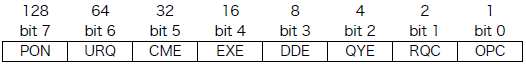
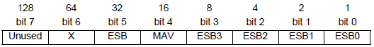
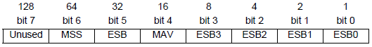
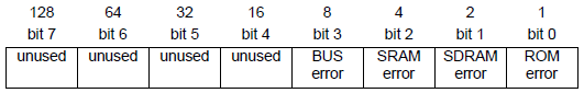
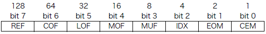
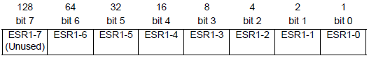
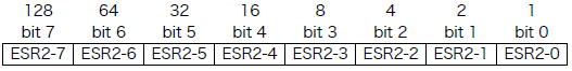
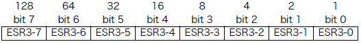
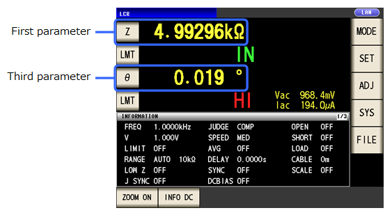
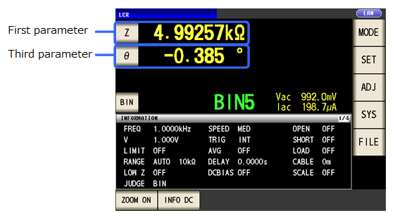
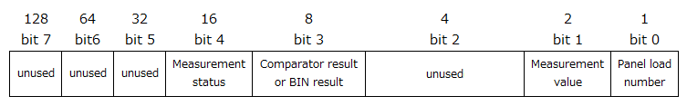
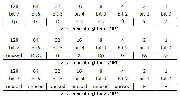
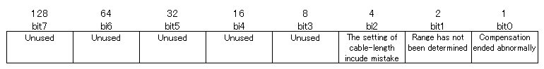
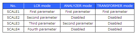
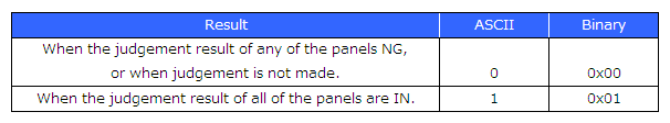
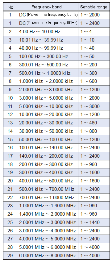
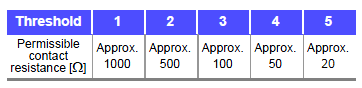
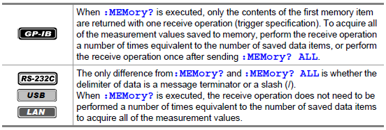
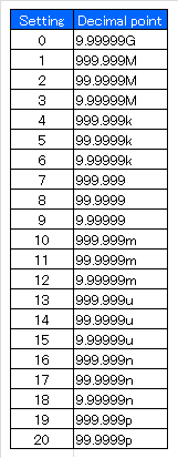
 " is saved.